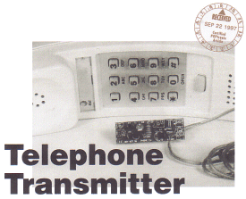
"Telephone Transmitter, FM."
"Receive telephone conversations on any FM radio with this neat little device."
FM Telephone Transmitter, Telephone, Transmitter
by Marc Spiwak
Would you like to be able to amplify a phone call so everybody can hear it? Or perhaps you'd like a way to record
phone calls for record-keeping purposes. If either idea sounds good to you, then you might want to build the FM
Telephone Transmitter describe in this article. It's a simple, yet ingenious device that connects in series with
a phone line, "reals" power from the latter, and transmits both sides of a conversation to an FM radio tuned to between
90 and 95 MHz.
The circuit is built on a PC board that is so small it can easily be fitted inside the housing of a telephone making it
an instant pseudo-speak earphone. Keep in mind, though, that it is illegal to listen to or record a telephone
conversation without informing all involved parties.
There are many legitimate reasons for wanting to broadcast a telephone call to an FM receiver. For one, maybe you are
calling one of those "900" information or entertainment lines, and everybody wants to hear the message. Or perhaps,
when someone calls long distance, he or she doesn't have the time or can't afford to stay on long, but everybody at
home still wants to hear his or her voice. Or perhaps you want to record a phone call so that you have a record of
some electronic banking you did or deal you made.
Besides being small in size, the Telephone Transmitter is also "small" in price. Only a handful of parts is needed to
build the project, and everything you need (including a PCB) can be purchased as a complete kit.
FM Telephone Transmitter, Telephone, Transmitter
 Circuit Description:
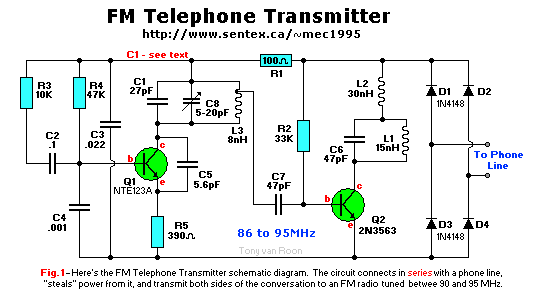
The schematic diagram for the Telephone Transmitter is shown in Fig. 1.
That circuit connects in series with either the Tip OR Ring, (green or red) leads of the telephone line.
Power for the circuit is full-wave bridge rectified by diodes D1 through D4. The other 2 wires are black and yellow and
are unused in most residences, unless you have a second line somewhere.
Transistor Q1, capacitors C1 and C8, and inductor L3 form an FM oscillator that operates at a frequency of around 93
MHz. Variable capacitor C8 allows the oscillator frequency to be adjusted between 86 and 95 MHz. To move the tuning
area up to the 90 - 95MHz range, C1 must be replaced with a 22pF capacitor. The tunable area can be moved even higher,
to over 100MHz, by replacing C1 with a 15pF or 10pF capacitor. Assuming the on-hook voltage is the standard 48V, like
in Canada and most US states. If the on-hook voltage of an extension phone network is lower, say about 39V, C1 will
have to be lower in the 15pF to 10pF to be tuned in the commercial FM band.
Audio from the phone line is coupled through R3 and C2 to the base of Q1 where it frequency modulates the oscillator.
Transistor Q1, inductor L1, and capacitor C6 form a power amplifier circuit. The signal tapped off L3 in the
oscillator circuit is fed to the base of transistor Q2 and the FM signal is transmitted from Q2's collector. Inductor L2
is a radio-frequency shunt that decouples power and audio from the amplifier circuit.
FM Telephone Transmitter, Telephone, Transmitter
 Construction:
The circuit is simple enough to build on perforated construction board, but the tight design of the PCBoard shown in
Fig. 2 is more desirable. If you would like to use a PCB, you can either use the foil pattern provided in that figure
to make your own PCB, or order a pre-etched and drilled board as part of a complete parts kit available from the source
given in the Parts List.
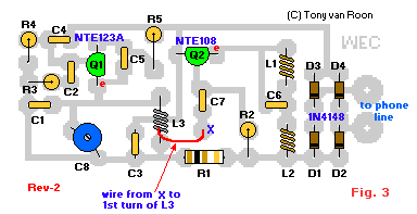
When mounting parts to the PCB, use the parts-placement diagram shown in Fig. 3 as a guide. Begin by installing the
resistors and diodes; the board is so thight that those components must be mounted vertically. The printed circuit board
measures 20x50mm (1x2"), so it is small. Resistors have to be mounted 'standing up'. Depending on the size of C8, the
trimmer capacitor, you may have to solder two pieces of wire to the legs of C8 and mount it that way. Either way, it is
a tight space.
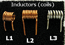
 The next step is to install the inductors. Coils L1 and L2 are six and eight turns, respectively, of enameled copper
wire. If you are winding your own coils, use approximately 22-gauge wire and a 1/8 inch drill bit as your winding
form. Any enamel on the leads where the coils are to be soldered must be sanded, scraped, or burned off with a
soldering iron before solder will adhere to them properly. Coil L3 is six turns of tinned copper wire in which the
coils must be spread out with about 1 millimeter between each turn; none of the turns are allowed to touch each other,
or the printed circuit board itself! After you are done spreading out the windings of this coil, the total width will
measure approximately 3/8" (9mm). Again, this is approximately and depending on your skill. Don't worry too much about
it. You can always spread it out more or squeeze it a bit when the coil is mounted.
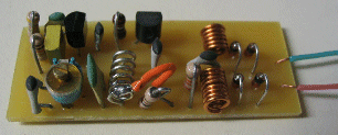
A tap is connected between the top of the first turn of L3 and the PC board (see picture).
Go on to install the fixed capacitors and the variable one (C8). Again, C8 may need some bending. Also, this cap may have
3 legs, you can cut 1 off and leave one side+walker in place. Safes on space on the PCB.
Then you can solder the two transistors to their appropriate places.
Be certain to inspect the board for errors before connecting it to the phone line. The range of the Transmitter is
less than 100 feet. That distance can be increased, however, by soldering a wire antenna (about 5 feet (150cm) of 26
gauge wire) to the collector of Q2.

FM Telephone Transmitter, Telephone, Transmitter
Test and Tune:
Connect the Transmitter to the phone line using whatever method you prefer. Just make sure it is connected in
SERIES. with just one (1) of the two wires!
This means cutting either the RED(Ring) or GREEN(Tip) wire and hook the circuit up in between the
one wire you just cut.
Turn on a nearby FM radio and tune to a quiet spot (no station using that frequency) on the dial somewhere between 85 and
95 MHz. Pick up the phone; you should here the dial tone right away on the FM radio. If that is not the case, adjust
 C8 until you do hear the dial tone. First adjust C8 for the best reception, and then fine tune the radio.
Should you have trouble finding a spot on the dial that is quiet enough, remember that the tuning area can be moved up
to the 98- to 105 MHz range by replacing C1 with a 10pF capacitor. Using a 22pF cap will tune the 90 to 95MHz range.
These ranges are also dependible on the coil-spacing.
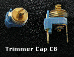
The picture of C8 shows a blue color which was used for the prototype. The actual color of this trimmer capacitor is
changing as rapidly as the weather(current color is red). Since the printed circuit board is so small, components
may have to be 'bend' in place, like C8 and the three coils, L1, L2, and L3. (Don't forget to scrape the coating of
the ends before soldering!). All other components mount best 'straight-up'.
And don't forget to solder a piece of wire at the first turn of L3 to the pad on the circuit board (see photo).
One last piece of advise, take your time inserting the semiconductors and ensure their posistion is correct before
soldering!
Parts List:
Semiconductors:
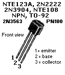
   Q1 = 2N3904, NTE123A, BC107, PN100, 2N4401, 2N2222, etc.
   Q2 = 2N3563, or NTE108, *ONLY!*
D1-D4 = 1N4148, signal diode

Resistors, 1/4W, 5% tolerance:
R1 = 100 ohm (brown-black-brown)
R2 = 33K (orange-orange-orange)
R3 = 10K (brown-black-orange)
R4 = 47K (yellow-violet-orange)
R5 = 390 ohm (orange-white-brown)

Capacitors:
   C1 = 27pF, ceramic
   C2 = 0.1uF (100nF), ceramic
   C3 = 0.022uF, (22nF) ceramic, 100V type
   C4 = 0.001uF, (1nF) ceramic
   C5 = 5.6pF, ceramic
C6,C7 = 47pF, ceramic
   C8 = 5-20pF trimmer cap

Additional Parts and Materials:
  L1 = 15nH (nanoHenry), 6 turns of #22 enameled copper wire (see text)
  L2 = 30nH, 8 turns of #22 enameled copper wire (see text)
  L3 = 8nH, 6 turns of #22 tinned copper wire (see text)
 PCB = Printed Circuit Board
Optional: miniature aligator clips

If you wish to purchase this project as a KIT, please [CLICK HERE]
FM Telephone Transmitter, Telephone, Transmitter
Copyright and Credits:
Original Project © by Mark Spiwak. Published in PopTronix Magazine, 1997, by Gernsback
Publishing. (Gernsback Publishing and POPTronix Magazine are no longer in business). Printed Circuit Board, Lay-out,
and photographs, copyright © 2005 by Tony van Roon.
Disclaimer:
Just for the sake of legal issues, below is our little disclaimer.
Depending on your country or state (province), most telephone companies don't like anything hooked up to their phone
lines. As such, by reading this disclaimer, you understand and agree to use this circuit at your own risk. The
University of Guelph, and/or Tony van Roon, can not and will not accept any liability at any time and/or for any reason
for the use or implementation of this circuit. This circuit may be used to share or record conversations but is not
intended for illegal activities. To use this device legally, you must inform your party that the conversation is
being recorded or monitored.
Back to Circuits page
Copyright © 2001 - Tony van Roon
Last updated: October 13, 2010


 Circuit Description:
 Construction:
 The next step is to install the inductors. Coils L1 and L2 are six and eight turns, respectively, of enameled copper
wire. If you are winding your own coils, use approximately 22-gauge wire and a 1/8 inch drill bit as your winding
form. Any enamel on the leads where the coils are to be soldered must be sanded, scraped, or burned off with a
soldering iron before solder will adhere to them properly. Coil L3 is six turns of tinned copper wire in which the
coils must be spread out with about 1 millimeter between each turn; none of the turns are allowed to touch each other,
or the printed circuit board itself! After you are done spreading out the windings of this coil, the total width will
measure approximately 3/8" (9mm). Again, this is approximately and depending on your skill. Don't worry too much about
it. You can always spread it out more or squeeze it a bit when the coil is mounted.


 C8 until you do hear the dial tone. First adjust C8 for the best reception, and then fine tune the radio.