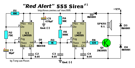
Parts List:
R1,R4 = 10K                          C1 = 10uF/25V, electrolytic
   R2 = 75K                    C2,C3,C4 = 0.01uF (10nF), ceramic
   R3 = 1K                           C5 = 470uF/25V, electrolytic
   R5 = 100K                    IC1,IC2 = 555 Timer/Oscillator
   Q1 = 2N3055                 D1,D3,D4 = 1N4001
   LS = Loudspeaker, 8 ohm           D2 = 1N4148
Notes:
The circuit above provides a 'pulse-tone', like the one you know from the old Star Trek. The output stage contains a
power-booster with Q1 (2N3055), providing several watts to the loudspeaker SPKR1.
Clamping diodes are used to limit the speaker's inductive kickback to a safe level. To prevent the output signal from
feeding back into the 555's via the supply line, the supply lines are filtered by a capacitor and an isolating diode
(C5 and D2).
This circuit acts as a pulsed-tone alarm-call generator. Integrated circuit U1 acts as an 800-Hz tone generator, and
is gated on and off once per second by U2 via D1.
Back to Circuits Page
Copyright © Tony van Roon

