Active FM Amplifier:
Parts List:
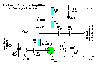
R1 = 27K
R2 = 270 ohm
R3 = 1K
Tr1,Tr2 = 22pF, trimmer cap (15-40pF)
C1,C2 = 5.6pF
C3 = 0.001uF (1nF), ceramic
C4,C5 = 0.01 (10nF), ceramic
C6 = 0.1uF (100nF), ceramic
Q1 = 2SC2498, 2SC2570, 2N5179, SK9139, or NTE10. NPN VHF/UHF transistor
L1 = 4 turns of 20SWG magnet wire, 5mm diameter. (so-called 3T+1)
L2 = 3 turns of 20SWG magnet wire, 5mm diameter.
With only a small handfull of parts you can built this trusty FM Amplifier.
This amplifier will pull in all distant FM stations clearly. The circuit is configured as a common-emitter tuned RF
pre-amplifier wired around VHF/UHF transistor Q1.
All capacitors are ceramic, and 50V is the standard but the 25V types work fine too. Trimmer capacitors Tr1 and Tr2
(22pF) are adjusted for maximum gain.
Input coil L1 consists of 4 turns of 20SWG enamelled copper wire over a 5mm diameter former. It is tapped at the
first turn from the ground lead side. Coil L2 is similar to L1, but has only three turns. Pin configuration
is shown in the diagram.
Source: "Popular Electronics" magazine, Copyright © Gernsback Publications, Inc.
1996. (Gernsback is no longer in business since January 2000).
Back to Circuits page
Copyright © 2003 - Tony van Roon