Alternating ON-OFF Switch, #2
Parts List
Resistors are 1/4 Watt, 5%
Alternating ON-OFF Switch, #2
R3,R5,R6 = 1K (brown-black-red)
   R1,R7 = 2K7 (red-violet-red)
      R4 = 100K (brown-black-yellow)
      R2 = 180K (brown-gray-yellow)
      C1 = 10uF/16V, electrolytic
      C2 = 220uF/16V, electrolytic
      C3 = 1uF/16V, electrolytic
      D1 = 1N4148, 1N4001, etc.
    Led1 = Led, any type/color
   Q1,Q2 = BC557B (or 2N3906)
      Q3 = BC337-40 (or 2N3904)
      S1 = Momentary on-switch
     Ry1 = Relay (see text)

A KIT (no pcb) for this project is available here: [Alternating ON/Off, Xtor]
Description:
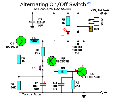
This circuit is the transistor version of the 4069 cmos type. Every press of the push-button will activate or
de-activate the relay. If you decide to mofify the circuit for 9V or higher, make sure the working voltage of
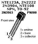
the electrolytic capacitors are 25V instead of 16V. The BC557B and BC337-40 are European transistors manufactured
by Philips in the Netherlands. Replacements such as the 2N3406(PNP), 2N3904(NPN), are okay, just watch the pin
orientation which differs in regards to the collector/emitter.
On power-up, the voltage on the base of Q1 and Q2 is equal with the supply voltage. The base of Q3 is at ground
potential. So, all three transistors are blocking. Relay Ry1 not energized and the Led is off.
Pressing momentary switch S1, Q2 is biased. After a small delay, caused by capacitor C1, Q3 is also biased. The
collector of Q3 is now put to ground potential, which causes relay Ry1 to energize and light the led at the same time.
At this time Q1 is biased and the circuit stabilized, because the base of Q2 is now connected to ground potential via R1.
This keeps Q2 biased when S1 is released (like a latch). C1 is recharged via R3, close to the supply voltage.
If S1 is pressed again, Q2's base gets biased with a positive voltage instead of being put to ground potential. Q2 will
block and the whole sequence will repeat itself. This circuit works like a thyristor. In fact, Q2 and Q3 are together
a discrete thyristor.
This circuit can be used in many applications by selecting different relays.
The coil of Ry1 should be capable of handling 5 to 12V at 250mA maximum or Q3 will go up in smoke!
The prototype used 70mA and less than 0.1uA when idle.
Back to Circuits page
Copyright © 1995 -- Tony van Roon
Last updated: August 29, 2010


R4 = 100K (brown-black-yellow) R2 = 180K (brown-gray-yellow) C1 = 10uF/16V, electrolytic C2 = 220uF/16V, electrolytic C3 = 1uF/16V, electrolytic D1 = 1N4148, 1N4001, etc. Led1 = Led, any type/color Q1,Q2 = BC557B (or 2N3906) Q3 = BC337-40 (or 2N3904) S1 = Momentary on-switch Ry1 = Relay (see text) A KIT (no pcb) for this project is available here: [Alternating ON/Off, Xtor]