"Join a growing crowd of DX' listening enthusiasts who regularly tune in commercial
air-to-ground and ground-to-air aeronautics communications. With this sensitive receiver you can hear them all, 747,
A380, Piper Cubs, Fedex, and others! Picks up transmissions up to 130 miles away."
If, like many scanner enthusiasts and ham operators, you are interested in listening in on all the excitement manifest
in aeronautic communication, but lack the equipment to pursue your interest, then maybe the Aviation-Band Receiver
described in this article is for you. The Aviation Receiver, designed to tune the 118-135MHz band, features exceptional
sensitivity, image rejection, signal-to-noise ratio, and stability. The receiver is ideally suited to listening in on
ground and air communication associated with commercial airlines and general aviation.
Powered from a 9-volt alkaline battery, it can be taken along with your to local airports so that you won't miss a
moment of the action. And even if you're nowhere near an airport, this little receiver will pick-up all the
ground-to-air and vice-versa communications of any plane or ground facility within about 130 miles (190Km).
Circuit Description:
Figure 1 shows a schematic diagram of the Aviation Receiver--a super heterodyne AM
(Amplitude Modulated) unit built around four IC's: an NE602 double balanced mixer (U1), an MC1350 linear IF
amplifier (U2), an LM324 quad op-amp (U3), and an LM386 audio amplifier (U4).
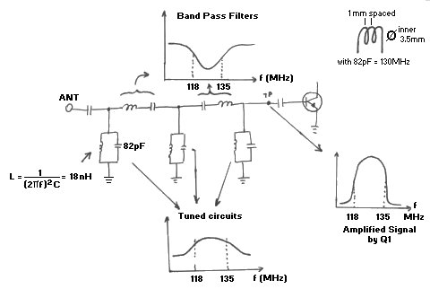
In operation, an antenna that plugs into J1 picks up the AM signal. That signal is then coupled through C1 to a
three-section, tuned-filter network consisting of L1-L5 and C2-C6. Signals in the 118-135Mhz VHF (Very High Frequency)
range are coupled through C7 to a VHF transistor (Q1), where the signals are amplified. From there, the signals are
fed through C8 to the input of U1 (the NE602 is a double balanced mixer), which in this application serves as a local
oscillator. A variable inductor (Local Oscillator L6) and its associated capacitor network set the local oscillator
frequency 10.7-MHz higher than the incoming 118-135MHz signals. A tuning network , consisting of varactor diode D1
and potentiometer R1, allows the local-oscillator frequency to be tuned across about 15MHz.
The 10.7-MHz difference between the received signal and the local-oscillator (LO) frequency (i.e., the Intermediate
Frequency or IF) is output at pin 4 of U1 to a 10.7-MHz ceramic filter (FIL1). The filter is used to ensure a narrow
pass band and sharp signal selectivity.
The output of FIL1 is amplified by Q2 and then fed through C16 to U2 (an MC1350 IF amplifier), which, as configured,
also offers Automatic Gain Control (AGC), as we'll see shortly. The amplified 10.7-MHz IF signal is peaked using variable
transformer T1. The AM audio is then demodulated by diode D2. After that, the audio is fed in sequence through four
sections of U3 (a LM324 quad op-amp).
Note that a portion of U3-a's output signal is fed back through resistor R25 to the AGC-control input of U2 at pin 5.
That signal is used to automatically decrease the gain of U2 when strong signals are present or to automatically
increase U2's gain for weak signals. That keeps the output volume of the circuit within a comfortable listening range
regardless of the strength of the incoming signals.
The receiver circuit also contains a squelch circuit that is controlled by potentiometer R3, which is used to kill
random noise below a selected threshold level. When properly set, the squelch control virtually eliminates background
noise, so that all you near are incoming signals that can be brought up to a usable level. Potentiometer R2 controls
the overall volume fed through C26 to U4, an LM386 low-voltage audio amplifier. Due to the overall design and squelch
control, the audio output is quite low in background noise, and yet it's capable of driving simple communications
speaker or earphones to excellent volume levels.

Construction:
The Aviation Receiver was assembled on a Printed Circuit Board, measuring about 4-1/2 x 5-1/4 inches.
Fig. 2 shows a full-size template of that printed circuit board's layout.
Although most of the parts for this project are commonly available through conventional electronic component suppliers,
a source for some of the more difficult to find parts is given in the Parts List for those who prefer to do their own
shopping. If you opt to gather your own parts or your plan to use what you have on hand, keep in mind that the
circuit-board layout was designed to accommodate components of specific dimensions in some cases; jacks J1 and J2,
switch S1, transformer T1, and all three potentiometers, for example. However, the potentiometers can be any model if
you wish. Just wire them to the board.
Also note that either of the Siemens parts specified in the Parts list for varactor diode D1 will work, but both may
be difficult to find from hobbyist sources. However, the second unit (BB505) is available from
Allied Electronics.
However you go about collecting parts for this project, don't even think about building the receiver circuit without
the printed-circuit board. At the frequencies involved, the placement of every wire and part, and even part value is
critical for trouble-free performance.
Once you have obtained all of the components and the board for the Aviation Receiver, construction can begin. A
parts-placement diagram is shown in Fig. 3. When assembling the project, take special
care that polarity-sensitive components (electrolytic capacitors [keep leads as short as possible], diodes, and
transistors) are installed properly. Just one part installed backwards can cause grievous harm!
Inductors (Aircoils) L1,L3,L5 can be made easily on a 5mm drill bit. Before you wind them, scrape the enamel of each
end, about 5mm. Then wind the 1.5 turn (2-turns is okay too). I know it can be tricky especially if you have big
fingers like me.
Begin by installing the passive components (6 jumper wires, sockets, resistors, capacitors, inductors). Followed by
installing the active components; diodes, transistors, and IC's. Once the active components have been installed,
check your work for the usual construction errors; cold solder joints, misplaced or reversed-lead components, solder
bridges, etc. Once you have determined that he circuit has been correctly assembled, it's time to consider the
enclosure that will house the receiver.
The receiver's circuit board can be housed in any enclosure that you choose. Use the picture at the top of this
project as an example if you wish.
The antenna for the Aviation receiver can be as simple as a 21-inch length of wire or telescopic antenna, or you can
get a fancy roof-mounted aviation antenna. If you are near an airport, you'll get plenty of on-the-air action from the
wire or telescopic antenna. But if you're more than a few miles away, a decent roof-mount (or scanner) antenna offers
a big improvement.
Alignment & Adjustment:
Aligning the Aviation receiver consists of nothing more than adjusting the slug in the local-oscillator coil (L6) for
the center of the desired tuning range, and peaking the IF transformer (T1). The receiver can be calibrated using a
VHF RF signal generator, frequency counter, or another VHF receiver by setting R1 to its mid-position; remember that
you want to set the local-oscillator frequency 10.7-MHz higher than the desired signal or range to be received.
Then, using a non-metallic alignment tool--a metal tool of any kind will drastically detune the coil, making
alignment almost impossible--adjust the Local Oscillator coil L6 until you hear aircraft or aircraft communications.
If you find that you're receiving a lot of FM broadcase stations, then you have adjusted the slug too far down into the
coil. Turn it back until it is a bit higher than the coil form and try again.
Once you're receiving aircraft or airport frequencies, adjust T1 for the best reception. Typically, T1 is adjusted
2-3 turns from the top of the shield can. If you don't have any signal-reference equipment or alignment, and are not
yet hearing airplanes, your best bet is to pack-up the receiver and the necessary alignment tools, and head for the
nearest airport! If the airport has no control tower, visit a general aviation center on the airport grounds, and ask
which are the most active frequencies. Then adjust L6 and R1 until you hear the action. It should be obvious that
alignment will test your patience if you do not live near a large airport.
Stretching L1, L3, and L5 at the antenna input will provide greater sensitivity if you have problems receiving a signal.
Also, as mentioned before, ensure that L1, L3, and L5 are mounted a *little* bit above the pcb.
A ground-service operator or private pilot may be willing to give you a brief test transmission on the 122.8 Unicom
frequency. And if your airport has ATIS transmissions you can get a steady test
signal as soon as you are within line-of-sight of its antenna. (See the explanation of Unicom and ATIS down the bottom
of this document). It is best to align the receiver right there at your local airport.
OMNI and VOR Transmissions:
If you can locate a tall white "cone" type of structure at your local airport or anywhere else such as a farmers field,
then you have found a "VOR" or "OMNI" beacon, a VHF navigational aid for pilots. If you can find this (steady) signal
it might help you in initial alignment of your receiver. Remember that you have to increase the local oscillator
frequency later on in order to listen to air traffic communication.
Troubleshooting Suggestions:
If the receiver does not work at all, carefully check the obvious things first; battery wires and switch, and the
connections to the speaker jack. Also, be sure to check that you've correctly installed all of the jumpers. If the
circuit's operation is erratic, a solder connection is usually the culprit, or there could be break in the antenna or
speaker wire. Did you install all 6 wire jumpers?
Pay special attention to the orientation of all IC's, transistors, diodes, and electrolytic capacitors. Also, be sure
that C11 and C12 in SA602 (U1's oscillator circuit) are of the correct values. Local-oscillator operation can be verified with
a simple VHF receiver or frequency counter. Remember that the local oscillator should be set to a frequency 10.7-MHz
above the desired listening range. If the oscillator works, only a defective or incorrectly installed part can prevent
the rest of the receiver circuit from functioning.
What You Can Expect to Hear:
No matter where you live, you will be able to receive at least the airborne side of many air-traffic communication. If
you know where to tune, you can hear any aircraft that you can see, plus planes a hundreds miles away and more, since
VHF signals travel "line-of-sight". Aircraft travelling at 45,000 feet and in "line-of-sight", can be heard.
Similarly, whatever ground stations you may hear are also determined by the line-of-sight character of VHF
communication.
If there are no major obstacles (tall buildings, hills, etc.,) between your antenna and an airport, you'll be able to
hear both sides of many kinds of aviation communication. Be prepared for them to be fast and to the point, and for
the same airplane to move to several different frequencies in the span of a few minutes!
At most metropolitan airports, pilots communicate with the FAA on a "Clearance Delivery" frequency to obtain approval
or clearance of the intended flight plan, which is done before contacting ground control for taxi instructions.
From the control tower, ground movements on ramps and taxi ways are handled on the Ground Control Frequency, while
runway and in-flight maneuvers near the airport (takeoff's, local traffic patterns, final approaches, and landings)
are on the Tower Frequency. ATIS, or "Automatic Terminal Information System", is a repeated broadcast about basic
weather information, runways in use, and any special information such as closed taxiways or runways. Such broadcast
offers an excellent steady signal source for initial adjustment of your receiver, if you are close enough to the
airport to receive ATIS.
Approach Control and Departure Control are air-traffic radar controller that coordinate all flight operations in the
vicinity of busy metropolitan-airport areas. When you hear a pilot taking with "Jacksonville Center" or "Indianapolis
Center", these are regional ATC (Air Traffic Control) centers. The aircraft is really en-route on a flight, rather
than just leaving or approaching a destination. A pilot will be in touch with several different Regional Centers"
during a cross-country flight.
Airports without control towers rely on the local Unicom frequency for strictly advisory communications between pilot
and ground personnel, such as fuel service operators. The people on the ground can advise the pilot what they know
about incoming or outgoing aircraft, but the pilot remains responsible for landing and take-off decisions. Typical
Unicom frequencies are 122.8 and 123.0MHz.
The FAA's network of FSS (Flight Service Stations) keeps track of flight plans, provides weather briefings and other
services to pilots. Some advisory radio communication takes place between pilots and a regional FSS. If there is an
in your local area, but no airport control towers, the FSS radio frequency will stay interesting.
Pilot and Controller Talk:
Just to make sure you have a basic understanding of aviation chit-chat, here are a couple of examples what you may be
hearing on your receiver. Don't blame the Aviation Receiver if all you hear are short bursts of words that don't make
a lot of sense at first. Aviation communication is necessarily brief, but clear and full of meaning. Generally,
pilots repeat exactly what they hear from a controller, so that both know the message or instructions were correctly
interpreted. If you are listening in, it's hard to track everything said from a cockpit, particularly in big city
areas. Just to taxi, takeoff, and fly a few minutes, all on different frequencies.
Here's the meaning of just a few typical communications:
"Miami Center, Delta 545 heavy out of three-zero-five." Delta
Flight 545 acknowledges Miami Center's clearance to descend from 30,000 feet to 25,000 feet. The word "heavy" means
that the plane is a Jumbo-Jet, perhaps a 747, DC-10, or LT-1011.
"Seneca 432 Lima cleared to outer marker. Contact tower 118.7" The local Approach
Control is saying that the Piper Seneca with the N-number, or "tail-number" ending in "432-L" is cleared to continue
flying an instrument approach to the outer marker (a precision radio beacon located near the airport), and should
immediately call the airport radio control tower on 118.7 MHz. That message also implies that the controller does not
expect to talk again with that aircraft.
"Cessna 723, squawk 6750, climb and maintain five thousand". A controller is
telling the Cessna pilot to set the airplane's radar transponder to code "6750", and climb to and level off at the
altitude of "5000 feet".
"United 330, traffic at 9 o'clock, 4 miles, altitude unknown." The controller
alerts the United Airlines flight of radar contact with some other aircraft off to the pilot's left at a "9 o'clock"
position. Since the unknown plane's altitude is also unknown, both controller and pilot realize that it is a smaller
private plane not equipped with altitude-reporting equipment.
Parts List and other components:

Resistors:
All Resistors are 5%, 1/4-watt
                 R1,R2,R3 = 10K PCB mount potentiometers
R4,R9,R15,R16,R20,R21,R24 = 47K
    R5,R7,R11,R18,R25,R27 = 1K
                   R6,R28 = 270 ohm
           R8,R12,R17,R23 = 10K
                  R10,R14 = 1 Mega Ohm
                  R13,R22 = 33K
                      R19 = 100K
                      R26 = 22K

Capacitors:
       C1,C7,C8,C13,C16 = 0.001uF, (1nF)ceramic disc (102, 1N)
               C2,C4,C6 = 82pF, NPO ceramic disc (82, 82p)
                  C3,C5 = 3.9pF, NPO ceramic disc (3.9, 3P9)
 C9,C17,C19,C20,C28,C30 = 0.01uF, NPO (10nF)ceramic disc (10N, 103, or Y5P103)
C10,C15,C21,C25,C26,C31 = 4.7 TO 10uF, 25WVDC, electrolytic
                    C11 = 10pF, NPO ceramic disc (10p, 10J)
                C12,C14 = 27pF, NPO ceramic disc (27p, 27J)
            C18,C27,C29 = 100 to 220uF, 25WVDC, electrolytic
                    C22 = 0.47uF, 25WVDC, electrolytic
                C23,C24 = 0.1uF, 25WVDC, electrolytic (104)
(NPO = standard for 'low-noise'. Caps have a black top.)

Inductors:
L1,L3,L5 = 1.5 turns #28 gauge magnet wire (wound on #29 or 3.5mm drill bit,
              about 1mm spacing in between turns after installing to the pcb.
   L2,L4 = 0.33uH, molded inductor* (Sayal 2/$1.00) DigiKey M9R33-ND, or M7807-ND)
             *M9R33-ND is Phenolic and more expensive. M7807-ND is Epoxy coated.
              or Miller #9230-08.  Colors Orange-Orange-Silver.
      L6 = 0.1uH, 3.5 turns, slug-tuned coil (DigiKey TK2816-ND) or TOKO
             #E528SN-100061 (orange, 10x7mm, see picture)
      T1 = 10.7MHz, shielded IF transformer (Mouser 42IF122, Brown cap color)
    Fil1 = 10.7MHz, ceramic filter (DigiKey, Murata type)

Semiconductors:
U1 = SA602AN (see note 1)
U2 = MC1350 or NTE746
U3 = LM324 or NTE987
U4 = LM386 or NTE823
Q1 = *2SC2570 (C2570), or NTE107, (Different Pinouts--click here!) NPN UHF silicon transistor
Q2 = 2N3904, NPN transistor
D1 = BB505B, varactor diode
D2 = 1N270, OA95, 1N34, or NTE109, Glass Germanium Diode
D3 = 1N914, NTE519, 1N4148, BAX13, etc. glass silicon signal diode.

*Printed Circuit Board is shown for the NTE107.

Additional Parts & Materials:
  S1 = SPST switch, PC mount
  J1 = RCA jack, PC mount
  J2 = Subminiature phone jack, PC mount
  B1 = 9-volt alkaline battery
MISC = PCB materials, enclosure, 9V battery connector, battery holder,
       wire, solder, knobs for potentiometers R1/R2/R3, antenna, etc.

See [UPDATES] in regards to modifications and changes.

Printed Circuit Board (PCB) Fig. 2, and Parts Assembly diagram (layout) is shown in
Fig. 3 to make soldering the unit together a breeze!
Note: PCB pads for the ceramic 10.7MHz filter (Fil1) have been modified. The filter should fit perfectly now. Also,
L6 in the parts layout diagram has been updated to reflect the square type TK2816-ND coil from Toko (PCB updated April
2, 2005).

 Fig. 4. shows the finished assembly
without the enclosure. Make sure the antenna-hole in the enclosure is in-line with the one on the pcb. On mine I used
a stud with thread on both sides to enable me to use different length antenna's; all I have to do is unscrew the antenna
and screw another antenna back in place without taking the receiver apart. In regards to the battery holder; you can
also just use a piece of the double-sided foam tape if you wish.
Fig. 4. shows the finished assembly
without the enclosure. Make sure the antenna-hole in the enclosure is in-line with the one on the pcb. On mine I used
a stud with thread on both sides to enable me to use different length antenna's; all I have to do is unscrew the antenna
and screw another antenna back in place without taking the receiver apart. In regards to the battery holder; you can
also just use a piece of the double-sided foam tape if you wish.
Note 1: The SA602AN is an updated version of the NE405 type (made by Signetics). It
is pin-to-pin compatible, and made by Philips. An even newer version is the SA612 and is also fully compatible with
better filtering and noise suppression, it just has less gain at 45MHz. The SA602AN is a perfect match.
The SA602 is a rare and *very* hard to find IC and the price can be in the range of $4 to $6.00 in US currency.
Note 2: The varactor diode (D1) BB505 may also be difficult to get because it is
obsolete. There is no replacement type for this varactor.
Note 3: The pin-out for transistor Q1 is very different for either 2SC2570 or the
replacement NTE107. Click [HERE] for the diagram.
The following email was received by Matt Hagman to improve the performance:
"I found that the audio amplifier IC may require an 8ohm + 0.047uF load (in a snubber configuration) in order to
prevent the tendency to oscillate at high > 300KHz frequencies."
Power consumption is minimum, the optional Led indicator will only add about 12mA. Most parts can be
obtained via your local electronics store, mail-order, or a KIT.
Below is a picture explaining the importance to make the the coils L1, L3, & L5 as precisely as you can.
Some personal pictures showing a different kind of battery holder and a view of [inductors L1/L3/L5].
Abbreviations:
  ATIS - Automatic Terminal Information System.  Picked up usually close to the
         airport.  The terminal parking lot is great for this.
   ATC - Air Traffic (Radar) Control.  Control Towers everywhere in the world.
   FAA - Federal Aviation Association (USA/Canada)
   FSS - Flight Service Stations.  The FAA's own network of Flight Service
         Stations which keep track of flight plans, weather information, and
         other advisory communications.
Unicom - If an airport has no control tower of any kind, pilots rely on the
         local "Unicom" frequency dedicated only to advisory communications
         between pilots and ground personnel like refueling service operators.
         The typical Unicom frequencies aare 122.8 and 123.0 MHz.
   VOR - or "OMNI" transmissions.  VHF navigational aid operating in the
         118-135MHZ frequency range, just below air-ground comm range, sending
         a steady signal (beacon).  If you can receive this signal remember to
         increase the local oscillator frequency later to listen to all air
         traffic communications.
Required Tools:
Soldering Iron, WLC100
Rosin Core Solder, thin
Small Needle Nose Pliers
Small Side (diagonal) cutters
Patience, patience, patience.
Other Helpful Tools:
Small Stainless Steel tweezers
Magnifying Glass
Helping Hands, or other PCB holding device
Desoldering tool, like braid, pump, etc.
Good Notes:
Tunes entire 118 -136 MHz Aviation band.
Easy tuning using one IF coil and one tuning coil (L6).
Operates on regular 9 volt alkaline battery.
Range 130 miles max (approximate) depending on type of antenna and location.
Receive control tower, aircraft-to-aircraft, maintenance, ground, ATIS, etc.
Squelch, and plenty of volume control.
Troubleshooting Help, again:
A "doesn't work" receiver can have a small problem or multiple problems related to the following examples below.
1 - Nothing works? Check for the obvious. Start with the Printed Circuit Board: check for solder splashes, hairline solder between
tracks, un-etched copper, 'cold' solder joints, etc.
2 - Polarity of IC's, electrolytic capacitors, diodes, battery clip, switch, loudspeaker, placement, etc.
3 - Correct flat-side position for the two transistors?
4 - Correct value of ceramic capacitors at the correct locations?
5 - Correct values for C11 and C12 in the SA602 oscillator circuitry?
6 - Did all the above and still no signal? Get out the assembly instructions and re-check everything! An incorrect
value resistor or capacitor is easy to miss.
7 - The working of the local oscillator can be checked with a simple VLF receiver or frequency counter. Remember that
it is supposed to be set 10.7MHz above the desired listening range. If the oscillator works, only a defective or
incorrectly installed part can prevent the rest of the receiver circuit from working.
Updates:
 2-09-2006  Added picture for D3 (1N914) to show 'Cathode' position.
 3-15-2006  Fine-tuned pcb again to fit new batch of different caps.  Adjusted
            spacing between tracks to eliminate risk of 'hairline' shorts.
            Modified pads for NTE107 (Q1) only.  Watch orientation!
 3-05-2007  Fine-tuned pcb to better fit the standard Hammond enclosure.
            Printed Circuit Board measures 395 x 475 pixels, 2 colors!
 3-26-2007  Spaced out the pads to fit the BB505 horizontally.  Note that it can
            be mounted 'standing-up'.
 1-01-2009  KIT version obsolete.  Some parts hard to obtain or expensive.
Copyright and Credits:
Source: "Electronics Hobbyist Handbook", Spring 1994. Copyright © Fred Blechman and
Gernsback Publications, Inc. 1994. (Gernsback Publishing is no longer in business).
Document updates & modifications, all diagrams, PCB/Layout, (C) Copyright by Tony van Roon.
Re-posting or taking graphics in any way or form of this project is expressly prohibited by international copyright laws.
Back to Circuits page
Page Copyright © 1995 - Tony van Roon
Project Copyright © 1994, by Fred Blechman (K6UGT)
Last Updated May 23, 2010