Although the compressors found in refrigerators, freezers, and air conditioners are heavy-duty devices, their life can
be shortened by frequent power outages, brown-outs, or other power glitches--unless you have a Compressor-Mate.
Description:
It's a great mystery how my development, which has an underground
power-distribution system, can have as many power failures as it does (at least two a month). Mystery or not, it's an
unpleasant reality that I and my electronic hardware must endure. I shudder to think of what people who live in really
windy areas with pole mounted distribution networks must put up with.
While everyone is aware of that a nuisance power outages are--what with having to reprogram the VCR, all the clocks in
the house, and a stubborn microwave that refuses to work unless informed of the time--many people don't know that
frequent outages can really cost them. If your local power is as unreliable as mine, the compressors in your home
appliances are probably taking a silent beating.
If a compressor is running at the time of a brown-out or intermittent power failure, it inevitable stalls and the
overload-protection circuit cycles on and off a few times. As any refrigeration specialist will tell you, starting a
compressor over and over under the load of compressed gas puts a lot of wear and tear on the equipment.
Since compressors form the heart of any appliance they're in, they don't come cheap. Depending on the age and cost of
a machine, an owner is sometimes better off buying a new appliance instead of replacing a compressor.
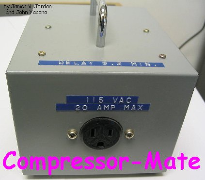
To protect your present (and future) investments, you can build a solid-state timer--the Compressor-Mate--that
will keep the compressors that you own from destructively cycling on and off. The project consists of a solid-state,
voltage-monitoring circuit with a five-minute delay timer controlling an electromechanical, 30-amp power relay.
The relay, in turn, controls power to the appliance being protected.
When power fails and comes back on, the Compressor-Mate waits about five minutes (more or less) before it restores
power to the appliance. That gives the unit time to cool down and permits system pressures to equalize for unloaded
restarting.
Beyond that, the project can be adapted to control AC or DC loads in the 24- to 240-volt range, so it can be used in
a variety of other applications. It requires a minimum of inexpensive, readily available parts. An avid hobbyist
could build one in a single evening, and even a beginner should have no trouble putting one together.
Parts List:
Semiconductors
U1 = CD4541, programmable counter/oscillator IC
Q1 = 2N5550, NPN transistor (NTE194)
SCR1 = T106D1, or similar, 4A/400PIV, sensitive gate SCR
D1-D4 = 1N4005, 1A/600-PIV rectifier diode.
D5 = 1N4739, 9V, 400mW, zener diode
Resistors
All resistors are 1/4W, 5%, unless otherwise specified
R1,R5 = 100 ohm
R2 = 4K7, Wire-Wound, 2 Watt (4700 ohm)
R3 = 33K
R4 = 4K7 (4700 ohm)
R6 = 6K8 (6800 ohm)
R7 = 150K
R8 = 220K
Capacitors
C1 = 0.047uF, 400WVDC, Mylar
C2,C3 = 10uF, 25WVDC, electrolytic
C4 = 0.15uF, 100WVDC, Mylar
*C5 = 1uF, 400WVDC, Polyester (optional)
Additional Parts and Materials
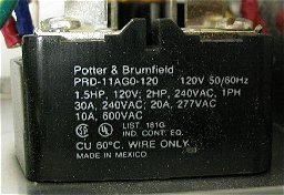
K1 = 30A DPDT power relay with 117VAC (or 220VAC) coil
PL1 - 3 terminal AC power plug with line cord, rated 15A or better
SO1 = 3 terminal AC socket, chassis mount, rated at 15A or better
Perfboard, metal enclosure, wire, solder, hardware, etc.
Also, keep a copy of the schematic diagram and a couple spare parts like the
CD4541 and the 2N5550 somewhere inside the enclosure for future usage.
The How's and Why's:
The compressor-Mate's schematic diagram is shown in Fig. 1. Although it can control a DC device, for the sake of
discussion let's first talk about how it operates when it controls an AC device.
The circuit can be broken down into two main sections: and AC portion, consisting of PL1, K1, and SO1; and a DC
portion, made of the rest of the components. Oddly enough, the coil of K1 (which is an AC led of the circuit) is in
series with the DC circuit via the bridge formed by D1-D4. That's important because whatever current flows through K1
must flow through the DC circuit.
When power is first applied to the circuit, perhaps after a power failure, the DC circuit draws very little current
(for reasons that will become obvious later). In fact, the current is so small that K1 is not activated. So when
power is first supplied, K1 is inactive and SO1 receives no power. However, after about five minutes, the DC circuit
draws lots of current, enough to engage the relay. So let's look at that portion of the circuit.
The bridge provides pulsating DC to a filter made up of capacitor C1 and resistor R1. The filter smoothes out the
pulsating DC and absorbs AC-line voltage transients to protect the other DC components. Zener diode D5, resistors R2
and R3, and capacitor C3 form a filtered-DC power supply. Resistor R2 limits current flow through D5 to a safe level.
That allows the diode to provide 9 volts to another filter comprised of C3 and R3.
The power supply supports a timing circuit. At the heart of the timer is U1, a programmable 16-stage binary counter
with an integral oscillator circuit, preventing the relay from engaging.
The counter is a multi-faceted device that can be programmed to act in a variety of ways. For example, its internal
oscillator can be replaced by sending the pulses of an external oscillator to pin 3. Whether you use the internal of
an external oscillator, the pulses are sent to an internal programmable counter/divider. Depending on the logic
levels presented to pint 12 and 13, the counter divides the pulses by 256, 1024, 8192, or 65,536. Because pin 12 and
13 are tied low, the counter divides by 8192.
The internal oscillator was used. It requires R7, R8, and C4 to set the frequency. The values specified for those
components set the frequency to around 26Hz. That might seem pretty slow, but the 4541 can operate with an oscillator
frequency of from close to DC to 100KHz. The oscillator (running at 26Hz) combined with the counter (dividing by 8192)
set the timing interval at about 315 seconds, or 5 minutes and 15 seconds.
The timer has an array of other features that the circuit takes advantage of. For example, tying pin 5 to ground, as
shown in the schematic, causes the timer to start timing on receipt of power. If that pin were tied high, the chip
would wait for a low-to-high transition on pin 6 before operating.
If a low is placed on pin 9, as shown in Fig. 1, the output of U1 at pin 8 goes low for the duration of a timing
interval. However, if pin 9 of U1 was held high, the output would be high during a timing interval. Pin 10, which
is connected to ground in the circuit, allows you to select between one-shot (if set to logic low) and astable (with
a logic high) modes.
To summarize, the timer is set up as a one-shot, power-activated, logic-low output timer with a period of 5 minutes,
15 seconds. So, when power is first applied to the circuit, the timer begins a timing interval and holds the output
of U1 at pin 8 low for about 5 minutes. The low power drain of the timer prevents K1 from latching.
When the interval is over, pin 8 goes high and provides sufficient base bias to Q1 via R6 to cause it to conduct. The
transistor then provides sufficient current to the gate of SCR1 through R5 to cause it to conduct. Capacitor C2 and
Resistor R4 prevent false triggering of SCR1. (Note that the diode bridge ensures that the SCR is always forward
biased.)
The voltage drop across the SCR is so small it effectively shorts the DC portion of the circuit and draws more than
enough current to cause K1 to latch. The relay, in turn, provides power to SO1, turning on anything connected to it.
Since the SCR is always forward biased, the relay remains on. If power is removed and re-applied, another timing
interval begins, permitting the device connected to SO1 five minutes to settle down before receiving power.
As was mentioned before, the device is suitable for DC applications. You will need to select K1, PL1, and SO1 to
suit your application. Although not needed for DC use, the diodes will make the unit immune to polarity reversal.
C5 is for absorbing possible spark when the contacts open. But optional. Any 400V capacitor is better than none.
Assembly and Testing:
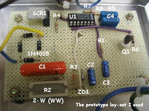
The DC portion of the circuit may be assembled on a piece of perfboard using point-to-point wiring, as in the prototype.
Be mindful of the orientation of diodes D1 through D4 and especially that of D5. The same holds true for capacitors
C2 and C3, as they are electrolytic units. Both Q1 and SCR1 are available in a variety of case styles and lead
configurations, so check their pin configurations before wiring them into the circuit. The use of a socket for U1 is
highly recommended, but do not install U1 untill called for during the test procedure.
When all components have been installed (except U1), check the wiring carefully. If you are satisfied that the wiring
is correct, strip the insulation from the ends of two leads and connect them to the AC points on the diode bridge.
The wire should be thick enough to easily carry current for the relay. Make sure that the relay can handle the load
you connect it to!
Wire the relay's coil in series with on of the DC circuit's two leads. Connect the appropriate connectors (PL1 and
SO1) to the remaining leads of the DC circuit and the relay. The wire that delivers power from PL1 to SO1 via the
relay should be selected to withstand the current needed by the device that you're protecting.
Check to make sure that the correct wires be connected to the correct pins on both PL1 and SO1
using the standard electrical code.
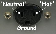
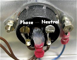
Like, the black AC wire (hot) is the narrow pin on PL1 and SO1 and the white wire (neutral) is connected to the wider
pin on both PL1 and SO1. Ground or 'Gnd' is connected to earth-ground; the center pin on both PL1 and SO1.
It is a good idea to test the circuit before placing it in an enclosure. When testing the unit, be sure to place it
on a non-conductive surface. Apply power to the unit; the power relay should NOT energize at this time.
If it does, remove power and recheck the wiring before going any further. If the relay coil does not pull in the
armature, but hums slightly, that is acceptable.
Remove power and take a piece of small diameter, insulated bus wire and jumper pins 8 and 14 of U1's empty socket.
(Never do this with U1 in place, it will destroy the IC.) Now apply power to the circuit. The relay should pull in
its armature and remain energized even if you remove the jumper wire (which you sho8uld do carefully if you are using
the project to control current).
Disconnect power to the project and carefully install U1 in its socket. Reconnect power tot the project. In 315
seconds, the power relay should energize. Momentarily interrupt the power. The relay should de-energize and then
re-energize again 315 seconds (approximately).
Note that during the first five timing cycles R2 will become warm and may smell. That's no cause for concern unless
the condition persists or if the resistor seems seriously overheated. If the tests go well, house the project in a
grounded metal box with holes cut out for the appropriate male and female power connectors.
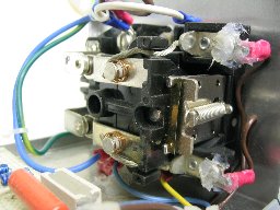
This concludes the testing and setup. You're all set to go. One more thing, make sure that the relay can handle the
current of your appliances or application! The prototype, as shown above, can handle 30A at 115V, but the SOCKET
receptacle *I* used can only handle 20A maximum! For other applications the receptacle can be eliminate of course and
the whole thing hard-wired. Just make sure everything is fire-safe.
Please Note: In some countries, states or provinces, it is *illegal* to
switch the neutral (white) wire. If your area has this regulation, then only the phase or 'hot' (black or red) wire is switched at the relay.
The neutral wire remains uninterrupted. Canada has this regulation so don't switch the neutral. -Tony
Copyright and Credits:
Source: "Popular Electronics", August 1991. Copyright © James V. Jordan and
John Yacono, published by Gernsback Publications (out of business in 2000), Inc. 1991.
Document updates & modifications, all diagrams, Layout, editing, © Copyright by Tony van Roon.
Re-posting or taking graphics in any way or form of this project is expressly prohibited by international copyright laws.
Back to Circuits page
Copyright © 2006 - Tony van Roon