"Learn the history behind the induction coil and the men that all invented it at once, and
then have a little high voltage fun for yourself".
Written by Tony van Roon and Stanley A. Czarnik
 The final quarter of the 19th century marked a period of extraordinary
scientific activity. Excitement was everywhere. Creative intellects flourished as the theory of evolution matured,
the camera innovated the study of the stars, and Freud contemplated the meaning of his dreams.
The final quarter of the 19th century marked a period of extraordinary
scientific activity. Excitement was everywhere. Creative intellects flourished as the theory of evolution matured,
the camera innovated the study of the stars, and Freud contemplated the meaning of his dreams.
During that same period, important contributions in the area of experimental physics were made. For example, in the
late 1800's, Heinrich Hertz produced the first ratio waves, which provided a concrete illustration of Maxwell's
theory of the identity of electromagnetism and light. In 1895, Wilhelm Roentgen stumbled upon the strange penetrating
power of the x-ray. In 1896, Guglielmo Marconi filed a patent application for one of the first wireless-communication
systems. And in 1897, Joseph John Thomson announced the discovery of the first sub-atomic particle: the electron.
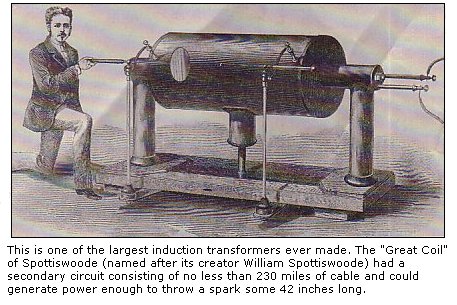
Of course, this list of discoveries in physics is selective and presented here to make a point. Every single
innovation in the sequence would have been difficult, if not nearly impossible, were it not for a a single piece of
laboratory equipment: the high-voltage induction transformer.
Just how, when, and where the induction coil was invented are not easy questions to answer. In fact, the entire
matter is submerged in a good measure of ambiguity and confusion. Let's try to disentangle some of the main
historical threads.
 Callan's Magnet:
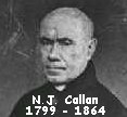
Nicholas Joseph Callan was born on December 22, 1799, the fifth child in a family of six or seven, at Darver, between
Drogheda and Dundalk, Ireland. His initial education was at an academy in Dundalk, run by a Presbyterian clergyman,
William Nelson. His local parish priest, Father Andrew Levins, took him in hand as an altar boy and Mass server, and
saw him start the priesthood at Navan seminary. He entered St Patrick's College Maynooth (near Dublin, Ireland) in 1816.
In his third year at Maynooth, Callan studied natural and experimental philosophy under Dr. Cornelius Denvir, who was
later to become Bishop of Down and Connor. Denvir introduced the experimental method into his teaching, and had an
interest in electricity and magnetism. After ordination as priest in 1823, Callan went to Rome, where he studied at
the Sapienza University, obtaining a doctorate in divinity in 1826. While in Rome he became acquainted with the work
which had been carried out by Luigi Galvani (1737-1798), and by Alessandro Volta (1745-1827), pioneers in the study of
electricity. On the resignation of Dr. Denvir, Callan was appointed to the chair of natural philosophy in Maynooth in
1826, and he remained in that post until his death in 1864.
 In December 1836, Nicholas J. Callan published a brief description of a "new Galvanic battery" in The London and
Edinburgh Philosophical Magazine. At the time, Callan was a clergyman and physics teacher at Maynooth College, in
County Kildare, near Dublin, Ireland. The battery consisted of 20 zinc plates, each about two feet square, and a
similar number of large copper cannisters to hold the acid. The system was activated by lowering the plates into the
acid by means of a windlass. Callan's cells required about 30 gallons of acid. The battery was quite powerful and
capable of melting thin pieces of platinum wire.
In December 1836, Nicholas J. Callan published a brief description of a "new Galvanic battery" in The London and
Edinburgh Philosophical Magazine. At the time, Callan was a clergyman and physics teacher at Maynooth College, in
County Kildare, near Dublin, Ireland. The battery consisted of 20 zinc plates, each about two feet square, and a
similar number of large copper cannisters to hold the acid. The system was activated by lowering the plates into the
acid by means of a windlass. Callan's cells required about 30 gallons of acid. The battery was quite powerful and
capable of melting thin pieces of platinum wire.
The generation of higher and higher levels of electrical energy seemed very important to Callan, and he proceeded to
discuss an alternative way of doing it. He took a bar of soft iron, about 2 feet long, and wrapped it around with
two lengths of copper wire, each about 200 feet long. For reasons left unmentioned, Callan connected the beginning
of the first coil to the beginning of the second. Finally, he connected a battery, much smaller than the enormous
 contrivance just described, to the beginning and end of winding one. He found that when the battery contact was
broken, a shock could be felt between the first terminal of the first coil and the second terminal of the second coil.
contrivance just described, to the beginning and end of winding one. He found that when the battery contact was
broken, a shock could be felt between the first terminal of the first coil and the second terminal of the second coil.
Further experimentation showed how the coil device could bring the shock from a small battery up the strength level
of a big battery. So, Callen tried making a bigger coil. With a battery of only 14 seven inch plates, the latter
device produced power enough for an electric shock "so strong that a person who took it felt the effects of it for
several days."
Callan thought of his creation as a kind of electromagnet; but what he actually made was a 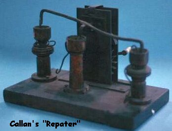 primitive induction
transformer.
primitive induction
transformer.
Callan's major claim to fame is as the inventor of the induction coil. Callan was influenced by the work of his friend
William Sturgeon (1783-1850) who in 1825 invented the first electromagnet, and by the work of Michael Faraday and
Joseph Henry with the induction coil. Working since 1834 on the idea of the induction coil, Callan developed his first
induction coil in 1836. He took a horseshoe shaped iron bar and wound it with thin insulated wire and then wound thick
insulated wire over the windings of the thinner wire. He discovered that, when a current sent by battery through a
"primary" coil (a small number of turns of thick copper wire around a soft-iron core) was interrupted, a high voltage
current was produced in an unconnected "secondary" coil (a large number of turns of fine wire). Callan's autotransformer
was similar to that of Page's except that he used wires of different sizes in the windings.
Callan's induction coil also used an interrupter that consisted of a rocking wire that repeatedly dipped into a small
cup of mercury (similar to Page). Because of the action of the interrupter, which could make and break the current
going into the coil, he called his device the "repeater." Actually, this device was the world's first transformer.
Callan had induced a high voltage in the second wire, starting with a low voltage in the adjacent first wire. And the
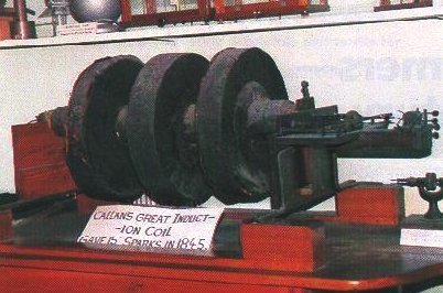
faster he interrupted the current, the bigger the spark. In 1837 he produced his giant induction machine: using a
mechanism from a clock to interrupt the current 20 times a second, it generated 15-inch sparks, an estimated 600,000
volts and the largest artificial bolt of electricity then seen.
The American Version:
 Callan was not the only one working with ways of increasing battery power by electromagnetic means. A few months
earlier, a similar system had been built in Salem, Massachusetts by a young medical student with a tireless interest
in electrical experimentation, Charles Grafton Page.
Callan was not the only one working with ways of increasing battery power by electromagnetic means. A few months
earlier, a similar system had been built in Salem, Massachusetts by a young medical student with a tireless interest
in electrical experimentation, Charles Grafton Page.
Charles Grafton Page was born in Salem, Massachusetts, 25 January, 1812. Page had read works by Faraday and Henry on
electrical induction, and as a result was able to construct a crude autotransformer (a device having only one coil but
acting as both a primary and secondary coil) that he called a dynamic multiplier. His multiplier was the first closed
core transformer and was used by Cromwell F. Varley in his coil design for which he received credit for the invention
in 1856. Page was a product of Jacksonian science, which subscribed to haphazard methodology without predetermined
goals. He rearranged the components of his multiplier in 1838 to build a new device. In the published 1839 description
he used the term "compound" to say that his magnetoelectrical machine used a common single magnet, and claimed that his
machine's output equaled a galvanic battery having 1,000 pairs of plates. His machine produced alternating current that
 was then converted into direct current by using a pole changer that he termed a "unitrep." His machine was then unique
because of its control or regulation of pulse frequencies by an attached device that he called an "electrotome." His
electrotome, however, was primitive and unlike the interrupters of the 1870s-1920s. His machine was too powerful to be
used in electrotherapeutics but it did have an effect on the future design of induction coils that were used in
medicine. In 1837, Page built a rocking magnetic interrupter or circuit breaker that was automatic for current altering.
This was the first magnetic operating interrupter for an induction coil.
was then converted into direct current by using a pole changer that he termed a "unitrep." His machine was then unique
because of its control or regulation of pulse frequencies by an attached device that he called an "electrotome." His
electrotome, however, was primitive and unlike the interrupters of the 1870s-1920s. His machine was too powerful to be
used in electrotherapeutics but it did have an effect on the future design of induction coils that were used in
medicine. In 1837, Page built a rocking magnetic interrupter or circuit breaker that was automatic for current altering.
This was the first magnetic operating interrupter for an induction coil.
From the late 1830s through the 1850s the induction coil grew into a marketable device with numerous improvements in
design and construction. Several notable individuals of science played a prominent role in its development during this
period of time such as: William Sturgeon (1783-1850), George H. Bachhoffner (1810-1879), Alexander Kemp, Christian Neef
(1782-1849), James W. McGauley (1806-1867), Dr. Golding Bird (1814-1854), and Dr. Guillaume Duchenne. Of course others
also made minor changes in the development of the induction coil, and these were mostly instrument makers such as:
Edward Palmer, Watkins & Hill, and E.M. Clarke. Englishmen dominated the development of the induction coil.
 Many new developments in electricity and magnetism took place during the 1820s when great scientists like Ampere,
Faraday, and Ohm dominated that area of science. Men like Clarke, Henry, Pixii, and Saxton became well known in the
1830s for their contributions to magnetoelectrical devices. Dr. Charles Page of the United States also became well
known in this country for his work in electrical science. He has been, however, somewhat of a riddle to historians who
have been undecided whether he was an inventor, scientist, or technician. Page was all three of these, and was an
individual who achieved acclaim more when living then after death. Maurer has called him an electrical experimenter,
while Rowbottom and Susskin stated that he was a designer of electrical experiments and instruments. Page was for sure
a physician and a scientist by education, and he functioned in these fields from the 1820s into the 1850s. He had for
years been engaged in perfecting machinery for the effective and economical use of electro-magnetism as a motive power,
and at the time of his death had so far succeeded as to be able to use it for the propulsion of machinery, and to some
extent as a locomotive force. In 1838 Page exhibited in London a locomotive propelled by battery power around a
circular railway track.
Many new developments in electricity and magnetism took place during the 1820s when great scientists like Ampere,
Faraday, and Ohm dominated that area of science. Men like Clarke, Henry, Pixii, and Saxton became well known in the
1830s for their contributions to magnetoelectrical devices. Dr. Charles Page of the United States also became well
known in this country for his work in electrical science. He has been, however, somewhat of a riddle to historians who
have been undecided whether he was an inventor, scientist, or technician. Page was all three of these, and was an
individual who achieved acclaim more when living then after death. Maurer has called him an electrical experimenter,
while Rowbottom and Susskin stated that he was a designer of electrical experiments and instruments. Page was for sure
a physician and a scientist by education, and he functioned in these fields from the 1820s into the 1850s. He had for
years been engaged in perfecting machinery for the effective and economical use of electro-magnetism as a motive power,
and at the time of his death had so far succeeded as to be able to use it for the propulsion of machinery, and to some
extent as a locomotive force. In 1838 Page exhibited in London a locomotive propelled by battery power around a
circular railway track.
 In a communication to "Silliman's Journal" dated May 12, 1836, Charles Page announced the construction of a device
for "increasing shocks" in a new way. That new way involved taking the shocks from a secondary winding longer that the
battery circuit. Recall that Callan's original coil was made with two windings of equal length. So, not only was Page's
coil made public before Callan's apparatus, it was different. In The history of Induction (1867), the one book
he wrote, Page described the novelty of his creation as follows: "the use of a longer coil for the secondary current
that used to transmit the battery current" and the production of "shocks from a pure secondary coil exterior to the
primary coil."
In a communication to "Silliman's Journal" dated May 12, 1836, Charles Page announced the construction of a device
for "increasing shocks" in a new way. That new way involved taking the shocks from a secondary winding longer that the
battery circuit. Recall that Callan's original coil was made with two windings of equal length. So, not only was Page's
coil made public before Callan's apparatus, it was different. In The history of Induction (1867), the one book
he wrote, Page described the novelty of his creation as follows: "the use of a longer coil for the secondary current
that used to transmit the battery current" and the production of "shocks from a pure secondary coil exterior to the
primary coil."
Page's first inductive device was unlike most of his later models. The prototype was a 220-foot long spiral of copper
ribbon mounted inside a wooden box. The coil was tapped in six different places with short copper strips connected
to open mercury cups on top of the box. That allowed Page to experiment with "sub-spirals" of various lengths. But
note: it's still one continuous winding of ribbon, not two.
Page's retrospective claim to have used a "purely" secondary coil "exterior" to the primary is somewhat misleading.
Strictly speaking, that's just not the case. Fact is, Page used a single winding with multiple taps; he had built, in
effect, an autotransformer.
In 1841, Dr. Page left medicine to take a job in the United States Patent Office in Washington, DC. He became one of
two principal examiners of the U.S. Patent Office. He resigned in 1852, but returned to the patent office in 1861 and
remained there until his death. He continued building and experimenting with electricity while he worked off and on
over the next 26 years as a patent examiner, examiner's adversary, and as a private agent. He taught night school in
the medical department of Columbian College (now George Washingon University) from 1844 to 1849. He built equipment for
Morse's telegraph, and like Joseph Henry's experience with Samuel Morse the association became a controversy over who
built the equipment.
 About 1850, Dr. Page received $20,000.00 in congressional support to build two special electromagnetic engines for a
locomotive. On 29 April 1851, the engines were ready for testing over 5 miles of track. After 1 mile and 39 minutes the
batteries supplying the engines of the train loaded with dignitaries failed near Blandensburg, MD. After repairs the
train took 2 hours to return to Washington. Page was convinced that with additional money the problem could be solved
and the electrical train could become a reality. Because of political delays, and President Johnson's impending
impeachment proceedings Page was never given the needed money. Page went into debt for the remainder of his life. Upon
his death his wife sued Western Union over her husband's patents that were never paid to him by the company. Dr. Page's
survivors lived more comfortably after his death than during his last several years of life. The money received by Page
from Congress was really one of the first grants for science, and it caused Page to become an outcast among scientists
in the United States because taking government money for research was considered unethical in 1850. Today, researchers
could not function if it was not for financial support from the government.
About 1850, Dr. Page received $20,000.00 in congressional support to build two special electromagnetic engines for a
locomotive. On 29 April 1851, the engines were ready for testing over 5 miles of track. After 1 mile and 39 minutes the
batteries supplying the engines of the train loaded with dignitaries failed near Blandensburg, MD. After repairs the
train took 2 hours to return to Washington. Page was convinced that with additional money the problem could be solved
and the electrical train could become a reality. Because of political delays, and President Johnson's impending
impeachment proceedings Page was never given the needed money. Page went into debt for the remainder of his life. Upon
his death his wife sued Western Union over her husband's patents that were never paid to him by the company. Dr. Page's
survivors lived more comfortably after his death than during his last several years of life. The money received by Page
from Congress was really one of the first grants for science, and it caused Page to become an outcast among scientists
in the United States because taking government money for research was considered unethical in 1850. Today, researchers
could not function if it was not for financial support from the government.
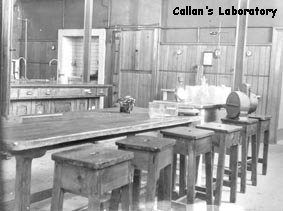
 Dr. Page invented a reciprocating electromagnetic engine and many other notable devices. In 1863, a mob of Union
soldiers broke into his laboratory and destroyed most of his equipment. Page never returned to science after that event.
Before his death he asked Congress to save his honor for the invention of the induction coil over the recognition given
to Ruhmkorff. Just before death in 1868, Congress passed a petition and gave Page his patents for recognition. This
petition also gave the Page family the right to sue companies using his devices without authority.
Dr. Page invented a reciprocating electromagnetic engine and many other notable devices. In 1863, a mob of Union
soldiers broke into his laboratory and destroyed most of his equipment. Page never returned to science after that event.
Before his death he asked Congress to save his honor for the invention of the induction coil over the recognition given
to Ruhmkorff. Just before death in 1868, Congress passed a petition and gave Page his patents for recognition. This
petition also gave the Page family the right to sue companies using his devices without authority.
Charles Grafton Page died in Washington, D.C., 5 May, 1868.
Simultaneous Invention:
In August, 1836, using a coil a bit larger than the one just discussed, Page succeeded in producing not only an electric
shock, but a very small electric spark between the terminals of a secondary winding. It seems clear that if just one
person must be given credit for the invention of the high voltage induction coil, it should be Charles Page.
Nonetheless, Nicholas Callan still deserves a measure of recognition; after all, he was working along similar lines with
similar equipment in the same year.
In his personal history, Page himself notes that he was the first one, but not the only one, to generate an induced
high voltage discharge in 1836. A spark, he mentioned, was also obtained by two Italian scientists, Antinori and
Linari, and published in the December 13, 1836 issue of L'indicatore Sanese. I have not been able to locate the
original Italian reference. Yet, it is possible, even probable, that crude high-voltage induction apparatus was being
 developed independently in not one, not two, but three different places--America, Ireland, and Italy--at almost exactly
the same time.
developed independently in not one, not two, but three different places--America, Ireland, and Italy--at almost exactly
the same time.
The Lightning Wheel:
Page had been in touch with William Sturgeon, a well-known English experimenter and inventor, in 1825, of the first
electromagnet. Sturgeon was also responsible for a science journal, The Annals of Electricity, and published a
reprint of Page's original article on increasing shocks in 1837. After that, interest in the new spark-producing
machinery grew rapidly, and improvements were announced one after another.
One special problem presented itself immediately. The high-voltage impulse in the secondary winding appeared only when
the primary circuit was opened or closed. So how to make and break the circuit in the most efficient way possible
became a point of major concern. As it turned out, there were a lot of ideas on how to do it.
One very early suggestion came from Neef and Wagner of Frankfurt-am-Main, Germany. It was a copper disc, about 6
inches in diameter, equipped with 36 strips of wood inlaid with strips of metal attached to the disc. A flexible
conductor made contact with the interleaved wooden and metal surfaces. When the rush hit metal, the circuit was
closed; when it hit the wood, the circuit was broken. Neef, a physician, used the system for the creation of a rapid
succession of presumably therapeutic electric shocks. He called his device the "lightning wheel."
The Hammer and the Wasp:
The lightning wheel, as well as other similar devices, had to be operated by hand. Such manual contrivances were
bothersome. What was necessary was some kind of automatic device
In September 1837, McGauley, of Dublin, exhibited the first self-acting circuit breaker. McGauley attached a soft iron
ball to one end of pivoted wire mounted over the induction apparatus. The ball was situated so as to be within the
electromagnetic filed produced by the core of the coil. The opposite end of the wire touched the surface of some
mercury placed in a small cup. When the system was activated, the magnetic field near the core of the coil attracted
the iron ball. That broke the contact at the surface of the mercury, shut down the magnetic field, and release the
ball. When the wire at the other end fell back into the mercury, the cycle would begin again.
A very simple mechanism, but it worked quite well and suggested itself elsewhere. Charles Page, without knowledge of
McGauley's experiments, came up with almost the exact same thing at just about the same time--yet another instance of
simultaneous invention and parallel channels of thought. Page made the automatic circuit-breaker part of his famous
"Electrostatic Coil" of 1838. According to A.F. Collins, writing in 1908, the so-called electrostatic machine
was the most powerful coil in existence at the time.
The next important development came, once again, from Neef and Wagner in 1839. In short, the men replaced the
mercury/cup arrangement with a vibrating metal strip and contact point and placed the entire sub-system at one end of
the coil. The great advantage of the device is obvious: it eliminated the mercury.
It did not take long for Neef's simple system, or something very similar to it, to become one favorite method of making
and breaking the primary circuit. Now, what to call it? One popular term was "rheotome" (current slicer). Page
liked "electrotome". Callan liked "repeater". Some preferred to honor the inventor with "Neef's Hammer". There were
regional variations too. In France, according to Becquerel, it was known as a "trembler" (trembleur). And of
course, among English-speaking experimenters, "interrupter" and "vibrator" were destined to become standard references.
Credit for the most imaginative expression must certainly go to a certain English clergyman and amateur physicist,
Reverend Lockey. Lockey noticed that the operation of a typical Neef-type device was accompanied by a kind of buzzing,
"a constant bee-like hum", as he put it. Apparently, he thought that the name of the mechanism should recall the
insect-like sound it made when it worked and suggested the term "galvanic wasp".
The Prize:
There is on final chapter in the story of the mid-19th century induction coil. In 1802, following a long visit by
Alessandro Volta, Napoleon Bonaparte announced the establishment of a 60,000-franc prize to be given to the creator of
the most useful application of the voltaic battery. The Volta Prize was awarded to Humphrey Davy in 1806. It was not
awarded attain for over fifty years. Following a revival of the competition by Napoleon III, the prize was given to
Heinrich D. Ruhmkorff in 1864 for the invention of the induction coil.
Yes, the invention of the induction coil. Heinrich Ruhmkorff did not invent the induction coil; there is no doubt
about that. So why, then, was he given the prize? Why not Charles Page? The reasons are very complex and, to this
day, not entirely clear.
In 1853, Armand Fizeau, a French physicist, discovered a way of greatly improving the performance of induction coils:
the connection of a capacitor parallel to the breaker points of the vibrator. That simple addition had the effect of
reducing unwanted discharge at the vibrator points and increasing the intensity of the secondary spark. Ruhmkorff,
who had been building induction apparatus at the Parisian workshop since 1851, incorporated Fizeau's modification
immediately. It was a good move at a good time. As Page himself said in 1867, Fizeau's contribution to the Ruhmkorff
coil "at once gave it a celebrity which perhaps, it might otherwise not have attained.
A Case of Indifference:
There is a wider issue implicated here, an issue involving the sociology of scientific activity. Recall for a moment
the period: the middle of the 19th century, almost 150 years ago. At the time, almost none of the major discoveries
in physics of electricity were being made in America; and perhaps important, non were really expected. Now, think of
the situation on the opposite side of the Atlantic. It could not have been more different. From Galvani to Volta, to
Davy, to Oersted, to Ohm, Ampere, Faraday, and beyond--everything, but everything, was coming from Europe. So, it
must have been only natural to believe that the trend would continue, and in many ways, it did.
Charles Page (much in fact, like Joseph Henry, the inventor of the electro-magnet) was the victim of a notorious
indifference to American science by 19th century European philosophers. When Ruhmkorff was recognized and rewarded
for the invention of the induction coil, it is likely that the French officials involved had never even heard of the
experimenter from Massachusetts. As Salem Howe Wales of Scientific American phrased it, the episode was yet
another "oversight of American achievements by European savants already too common." The real inventor of the
induction was not ignored; he was unknown.
A Spark Coil for your Home Lab:
A good electromechanical induction coil is still one of the most versatile and enjoyable high-voltage devices you can
possess. An excellent example designed along classical lines is currently available from Fisher Scientific, a
laboratory supply company in Chicago (see parts and materials list for more information).
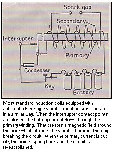
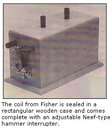
The coil is sealed in a rectangular wooden case (about 8x5x4 inches) and comes complete with and adjustable Neef-type
hammer interrupter. The unit is made to operate with a DC input of about 6 to 10 volts at between 0.5 and 3.5 amps
depending on input voltage and adjustment of the breaker points on the hammer. The input terminals are next to the
vibrator and the high-voltage output posts are on top--just as they were on the classical induction transformers of
the 19th century. The unit delivers a strong spark at least 1 inch long and power enough for most of the standard
high-voltage projects and demonstrations.
You will, of course also need a power supply. Anything that can supply the required voltage and current will work,
but one with a continuously variable output between 6 and 12 volts is recommended.
Assuming that you have gathered some of the things listed in the Parts and Materials List, let's discuss some
experiments you can perform. Keep in mind that these demonstrations, generate a certain amount of ozone; so you'll
want to perform all of your experiments in a well-ventilated room.
Parts and Materials List for the Induction Coil Experiments:
6-12volt, 0.5-3.5 amp DC power supply
Copper wire
15-inch fluorescent tube
Four 4x4 glass plates
Induction Coil
Iron filings
Large binding post of Fahnestock clip
Miniature mercury-vapor bulbs
NE-2 neon bulbs
Salt shaker
Sheet aluminum or brass, 4.5 x 2.5 inches
Spark plug wire (or equivalent)
Steel ring
Telegraph key
Threaded rod (or long narrow screw)
Wire screen 4-1/2 x 2-1/2 inches
1 piece of wood, 7-1/2 x 5-3/4 x 3/4 inches
2 pieces of wood, 5-1/2 x 1-1/2 x 1-1/2 inches

Note: The high-voltage induction coil is available from Fisher Scientific EMD
      (4901 W.LeMoyne, Chicago, IL 60651; Tel. 1-800-766-7000: as partnumber
      S-43525 for $121.10.  (www1.fishersci.com)

The following items are available from American Science and Surplus (601 Linden
Place, Evanston, IL 60202; Tel. 1-847-647-0011):
4-3/4 inches O.D. steel rings, part number 20247 at $2.50 for a package of two,
green mercury vapor glow lamps, part number 3628 at $2.25 for a package of three.
The company requires a $12.50 minimum order and a flat $4.00 fee for shipping and
handling.  Their catalog is available for 50 cents. (www.sciplus.com)

Clean 4x4 inch glass plates are available from Hagenow Laboratories (1302
Washington St., Manitowoc, WI 54220) as part number 67C for 49 cents each.  The
company requires a $15.00 minimum order.  Their catalog is $1.50.  WI residents
must add sales tax.  (Tony's Note: Hagenow Laboratories has been renamed to
Elemental Scientific, LLC, www.elementalscientific.net or www.hagenowlaboratories.com,
but their postal address remained the same.)
Testing and Operation:
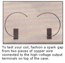
The most obvious thing to do with a spark coil is make a spark. For that, obtains two pieces of bare copper wire each
about 3 inches long. Do not use covered wire; the insulation may get hot and melt. Bend each of the pieces into a
semi-circle and connect them to the high-voltage terminals. The idea is to keep the two wires as far away from each
other except where they form the spark gap somewhere above and between the binding posts. To begin with, make the
spark gap about 1 inch across. Make sure the wires are fastened down tight.
Now, look at the vibrator mechanism. You will see a large knurled nut; that is the breaker-point adjustment control.
Screw the nut in or out until the points are just barely touching. Finally note polarity as indicated (by color) at
the input terminals of the coil and hook up your low voltage DC power supply.
If necessary, set the supply between 6 and 12 volts. Turning on the supply should cause the coil to produce a strong 1
inch spark. If it doesn't, turn the power off and loosen or tighten the control nut slightly. Make your adjustments
conservative, a quarter turn, perhaps; the operational range is not very large.
Do not attempt to touch the vibrator or adjust the points when the unit is in operation!
Once you get a spark, turn off the coil and make the spark gap about 1/4 inch larger. Then turn on the power and check
for a spark. If you have an adjustable supply, raise the input voltage a bit if necessary, but don't overdo it. You
can also try re-adjusting the vibrator. Repeat the procedure until the gap is too wide for a spark to pass. That is
one simple way to determine the maximum output of your coil.
When everything is just right, the system will deliver a thin, intermittent, lightning like spark close to 2 inches
long. These long sparks are best observed in a dark room.
Gaseous Tube Illuminator:
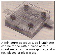
There are many, many things you can do with your induction coil. With some scrap metal and a few pieces of glass you
can make a miniature gaseous-tube illuminator.
Obtain four plates of clear glass about 4 inches square. Such glass plates are standard science items and can be
ordered from a supplier mentioned in the Parts and Materials List. You'll also need some clean wire screen and a piece
of very thin sheet metal (like brass or aluminum). The metal sheets you select should be thin enough to permit easy
shaping with scissors.
Cut the metal sheet to form a rectangle about 2-1/2 inches wide and 4-1/2 inches long. Then, fashion a tab at one
narrow end of the rectangle. Now, cut a piece of wire screen to match the size and shape of the metal sheet. The
metal sheet and wire screen will be uses as electrodes.
You're now ready to build the illuminator. Place the metal-sheet electrode between two of the glass plates.
Place the wire-screen electrode between the other two. Rest the sheet-metal sandwich on some sort of insulating
material, like a 4 x 4 inch block of wood. Now place a few small neon bulbs on the glass surface over the metal sheet.
Then, add four rubber spacers, one at each corner of the glass. Finish by placing the wire mesh arrangement carefully
over the bulbs; the lower glass plate should rest on the spacers. The tabs on the metal sheet and the wire screen should
be pointing away from one another.
Connect one high-voltage output terminal on the induction coil to the sheet-metal tab, and the remaining terminal to
the screen's tab. Spark-plug wire is probably the best kind of wire to use; but any sort of heavy, well insulated
hook-up cable will work. Finally, darken the room and turn on the power. A high voltage electric field is created in
the space between the plates that causes the neon tubes to flicker and glow like so many little lightning bugs.
You may observe a few stray sparks passing over and around the edges of the glass plates. A very careful re-arrangement
of the electrodes (with the power off, of course!) will probably solve the problem. If
it does not, try using smaller electrodes, larger pieces of glass, or a lower power-supply setting.
For an unusual multicolor effect, try replacing a few of the neons with small mercury-vapor lamps. The type I used
were also used in the Electronic Novelty Light featured in the December 1990 issue of Popular Electronics magazine.
See the Parts and Materials List for more information.
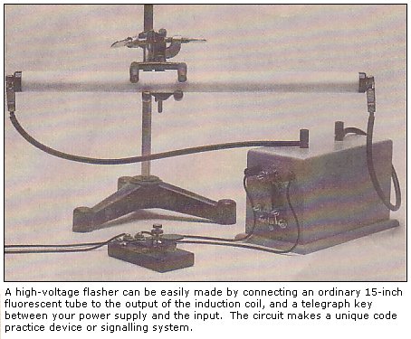
Fluorescent Flasher:
If you enjoy working with gaseous conductors, here's something else you can try. Obtain a good quality telegraph key
(or some other kind of momentary-contact switch) and hook it up in series between one output terminal of your power
supply and one input terminal of the induction coil. Now, locate an ordinary 15-inch fluorescent tube and connect it
directly to the high-voltage output with some spark-plug wire and a couple of alligator clips. To keep the whole
contrivance steady and safe, the fluorescent tube should be elevated up and away from the rest of the equipment with
a stand of some sort. For such temporary projects, standard laboratory hardware comes in very handy.
With the power supply on, each press of the key will activate the coil and flash the lamp. The circuit makes a unique
code practice device or signaling system. For a still better effect, try using a green fluorescent tube in place of
the conventional variety. Such tubes are often sold as replacement parts for photocopying machines.
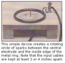
The Spark Ring:
Here's a device which will enable you to create an infinite variety of randomly rotating sparks. The visual effect
resembles a wagon wheel spinning under a strobe light. Frozen with a photographic time-exposure, it resembles some
sort of weird electric snowflake.
The simplicity of the spark ring allows for a number of equally suitable construction methods; but, here's one easy
way of doing it: To begin, you'll need some wood--one piece about 6-1/2x5-/12x3/4 inches and two pieces 5-1/2x1-1/2
inches square. Locate the exact center of the larger piece and drill a hole just big enough to accommodate a long
screw or length of threaded rod. The screw should extend at least 1/2 inch beyond the upper surface of the wood and
no more than 1 inch below the lower surface. Drill another hole (somewhere near the upper right hand corner is a good
place) for a large binding post or Fahnenstock clip. Set the piece aside for now.
Now for the key component: a perfectly circular ring of metal about 4 or 5 inches in diameter. You may very well have
something like that in your collection of building materials. If not, just make a loop from some thick wire, metal
tubing, or a long metal strip by wrapping it around a larger round bottle. Or, you can get something ready made.
What I did was obtain a big steel ring from American Science and Surplus (see Parts and Materials List). It's the
perfect size and shape. Also, it's heavy enough to stay in one place without the need for additional hardware.
Once you have your metal ring, you'll need to furnish it with a piece of flexible conductor for attachment to the
binding post. I used some braided copper ground cable, but a short length of stranded wire will do just as well.
If possible, solder the wire to the metal ring. Do not use too much wire to make the connection, otherwise the metal
ring may not lie flat on the wood. Then set the whole construction on the two remaining pieces of wood.
Cut two 15- or 20 inch pieces of spark-plug wire cable and furnish one of them with a large alligator clip. Connect
the clip to the threaded-rod electrode beneath the lower surface of the wood. Connect the other wire to the binding
post. Then connect the apparatus to the high-voltage output of the induction coil.
Finally, obtain some powdered iron and place about a tablespoon of it in an old salt shaker. Now, very carefully,
sprinkle some of the metal onto the surface of the wood inside the perimeter of the metal ring. Try to distribute the
iron as evenly as possible, but do not use too much of it.
When everything is ready, darken the room and turn on the coil The entire area inside the ring will light up with
hundreds of tiny sparks created by the gaps between the particles of iron. If you are not satisfied with the effect
at first, just turn the apparatus off, remove the iron particles with a magnet, and try again. Every application of
iron will create a slightly different pattern of sparks. The designs bear an interesting resemblance to the
Lichtenberg figures in an earlier article (March 1990).
Do not feel limited to the use of powdered iron. Any low resistance material reduced to the apparatus to the
appropriate size will work; but the effect will be different. You can try tiny bits of stranded copper wire, metal
foil, or even a small handful of miniature nuts and bolts. However, do not, under any circumstances, use an easily
combustible metallic substance, like powdered magnesium, powdered aluminum, or zinc dust. They are very, very
dangerous.
Also, keep in mind that the apparatus does create some heat in the central electrode and metal ring. So, do not run
the equipment for extended periods of time and watch carefully for anything suspicious or unusual, like over-active
sparks or scorched wood.
Learning More:
For more on the history of induction apparatus, see George Shier's May 1971 article in Scientific American and Robert
Post's biography of Charles Page. For more experimental ideas, see Volume II, Chapter 2 of George Hopkins'
Experimental Science and Chapter 5 of H.S. Norrie's Induction Coils. For additional information, consult
the section "Further Reading", and Tony van Roon's HV projects,
"High Voltage Projects you can Build".
Copyright and credits:
This article originally was written by Stanley A. Czarnik and the editors of "Popular Electronics" magazine,
March issue of 1992, and published by Gernsback Publishing (Gernsback Publishing is no longer in business).
Editor's note and Disclaimer:
The device carries lethal high voltage and carelessness can be dangerous to your health. Build and/or use at your own risk.
The Sentex Corporation of Cambridge Ontario, host of "Tony's Website", or Tony van Roon himself, cannot be held liable or
responsible or will accept any type of liability in any event, in case of injury or even death by building and/or using or
misuse of this device or any other high-voltage device posted on this web site. By accessing, reading, printing, or building
the unit in this article you agree to be solely responsible and agree with the above stated disclaimer.
Back to High Voltage Projects Index
Copyright © 2005 - Tony van Roon
Last Updated: July 24, 2010