Parts List
R1 = 3K3, 5%
R2 = 1M, 5%
R3 = 10 ohm, 5%
C1 = 0.1uF, monolithic capacitor
C2-C9 = 0.01uF 400 volt polyester capacitors
Dx = 1N4001
D1-D8 = 1N4007, 1000 Volt diodes
Neon = Type NE-2 neon bulb
Q1 = MJE521 NPN power transistor (40V/40W/4A), or TIP31C
Q2 = MJE371 PNP power transistor (40V/40W/4A), or TIP32C
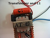
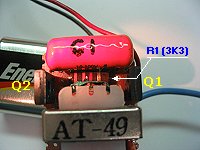
T1 = 1200:8 ohm audio output transformer (green), Armaco AT-49
or Mouser part number 42TU003, 400mW $2.19, or Mode 60-282-0 at $1.81
S1 = SPST momentary-contact, pushbutton switch
Updated 2-27-2005:
I updated this article and circuit diagram with suggestions from members of the Message Forum:
Al: "Q1 has no current limiter. It gets hot because the c/e voltage is always high even when fully on. Q2 must
pass this current thru its b/e junction. A 10 ohm resistor (R3) in series with Q1 collector will fix this. When Q2
switches off, its collector drops more than the supply voltage and this step voltage goes thru the cap to Q1 base
which reverse conducts. A diode(Dx) in series with Q1 base will protect the b/e from reverse breakdown damage."
Thanks Al, Jean, Michael, and others for your input. Much appreciated!
Additionally:
9-volt battery clip, 10 x 5 x 2.5cm plastic case, 7.5 x 4cm perfboard or pcboard, two 8/32 x 1-1/4 bolts
and nuts for electrodes, adhesive for mounting NE1, circuit board standoffs (optional), hookup wire, solder, etc.
Substitutes:
Q1 (MJE521), the NTE184, 2N5190, or TIP31C will work, and for Q2 (MJE371) the NTE185, 2N5193, or TIP32C will work.
T1: Mode 60-282-0 (Audio) about $2.00, Armaco AT-49 (Audio) about $5.00, Hammond 141P (Audio) about $19.00.
I have not experimented with the 1000:8 ohm type. Try it. No guarantees it will work. Why an audio output transformer?
The windings are much finer and the overall size of this transformer is much smaller than the average power transformer.
Compare it this way, holding a mini-cell phone versus a stone brick. Again, and just in case you don't know, the Audio
Transformer mentioned for this project is measured in OHMS (impedance) and not turns
or windings, and is an OUTPUT type. Not 'coupling' or 'isolation' or whatever.
 WARNING:
THIS DEVICE IS NOT A TOY! We present it for EDUCATIONAL and EXPERIMENTAL purposes ONLY. The circuit develops
about 2000 volts at a respectable amperage. It can cause you pain and even damage if you become careless and touch
its output terminals. The unit can also damage property as well so use it wisely. You should NEVER use the device on
another person! It may not be against the law to possess such a device in your area, but if you use it on someone you
may be deemed liable a a civil and/or criminal action suit. Don't just follow the golden rule after constructing the
project, instead just don't do it unto anyone. Included in the article are a number of instructions on how to build,
test, and operate the Dazer; all of them must be followed to the letter. Do not deviate from the procedure.
WARNING:
THIS DEVICE IS NOT A TOY! We present it for EDUCATIONAL and EXPERIMENTAL purposes ONLY. The circuit develops
about 2000 volts at a respectable amperage. It can cause you pain and even damage if you become careless and touch
its output terminals. The unit can also damage property as well so use it wisely. You should NEVER use the device on
another person! It may not be against the law to possess such a device in your area, but if you use it on someone you
may be deemed liable a a civil and/or criminal action suit. Don't just follow the golden rule after constructing the
project, instead just don't do it unto anyone. Included in the article are a number of instructions on how to build,
test, and operate the Dazer; all of them must be followed to the letter. Do not deviate from the procedure.
The Electronic Dazer is a modern, portable, non-lethal-personal-protection appliance. It generates hight
potential energy to ward off vicious animals or other attackers. It is an aid to help escape from a potentially
dangerous situation. the device develops about 2,000 volts. Higher voltages may be attained by adding additional
multiplier stages, but it should be noted that those stage(s) will also increase the overall size of the unit.
The Dazer is very compact, being built into a small plastic case. It is powered by a single 9-volt battery, either
NiCad or alkaline. (Editor's Note: the so-called 9-V NiCad
actually provides only about 7.5V. Why? NiCad cells only give 1.25 per cell. 6 cells in a 9volt battery gives it 7.5V
and so the Alkaline type would be a better choice).
The high voltage is applied to two electrodes which require only light contact to be effective. When touched with the
Dazer, the victim will receive a stunning, but non-lethal jolt of electricity that will usually discourage any further
encounters.
The electronic Dazer is aper supply which consists of a micro-size regenerative amplifier/oscillator coupled to an
energy multiplier section. It should not be confused with cheap induction-type cattle prods. The Dazer is more
versatile than other high-voltage stun devices currently being sold. Those devices are basically high-voltage, AC
generators which jam the nervous system. However, the Dazer may be used for heating and burning applications, or
anywhere a high voltage DC supply is required.
(Tony's Note: Don't confuse the Dazer with a Stun-Gun. The Dazer emits high voltage about 2000V DC,
a Stun-Gun can generate VERY High Voltages varying from 15,000V to 650,000VAC (as claimed by some
manufacturers), and can cause personal injury or even death. Stun-Guns are considered banned illegal fire-arms, you
risk criminal prosecution if law enforcement finds one in your possession (Canada, not sure about USA).
How it Works:
Referring to the schematic diagram, the two power transistors Q1 and Q2, form a regenerative amplifier operating as a
power oscillator. When Q1 turns on, Q2 turns on and that shorts the power supply across the primary of T1. That
current pulse induces a high voltage in the secondary of T1. As C1 charges, Q1 turns on again and the cycle repeats
itself. Therefore, a rapid series of DC pulses are generated and stepped up by T1 to approximately 300 volts at full
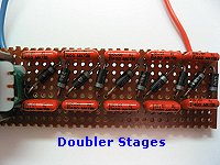
battery charge. That voltage is rectified and increased by the voltage multiplier section which consists of C2 to C9,
and D1 to D8. The final output is approximately 2000 volts. The neon bulb 'Neon' is used as a charge indicator and
indicates that the unit is charged and operating properly.
Check out fig. 1 at the right; these
are standard voltage doublers found in many data books and others like the NTE, Newark, or ElectroSonic catalogs.
They can even be found on the internet. Just do a search on one of the major search engines like Yahoo or Google and
search for 'voltage doubler' or 'HV'.
Electronic Dazer, High Voltage, Jacobs Ladder, Voltage Doubler, Ball of light
Construction:
As with all projects start out by laying out and identifying. If you do not wish to make a printed-circuit-board, then
you may use perf board as long as you remember to keep the leads of all high-voltage components isolated. That is to
prevent sparks from arcing across your board. A 4 x 7.5 cm of perfboard is suitable for that purpose.
The first components you should mount are the two transistors Q1, Q2, transformer T1, resistor R1, and neon bulb 'Neon'.
Solder them in place (for PCB construction) being sure that the transformer and transistors are hooked up correctly.
Apply a small amount of adhesive to the base of NE1 to hold it securely in place.
Mount D1 to D8 and C2 to C9 on the board and make all solder connections. Note proper polarity of the diodes. The
off-board components are next. Solder in leads for S1, and the output electrodes. Also solder in the battery clip
for B1.
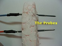
Build the enclosure from some nonconductive material such as ABS plastic. Drill holes for S1, Neon, and output
electrodes. Be sure that the output electrodes are about a cm or greater apart. Connect the output wires tot the
electrodes and insert them trough holes from inside of the case. Thread on the retaining nuts and tighten them securely.
Set the circuit board in the case and mount S1, securing with a nut. That completes the construction.
Testing:
Before inserting the battery and closing the case, a few test measurements should be
made to ensure correct operation.
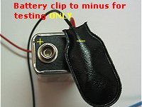
With the ground clip connected to the battery (do NOT connect the complete clip to the battery ONLY
the ground), connect a volt or multimeter between the positive clip and the positive terminal of the battery. Set the
meter for current reading, and press S1. You should measure a current of approximately 300 to 500mA. The 'Neon' light
should be glowing.
With a high voltage multimeter or VOM, you should measure about 2000 volts on the output terminals. Those measurements
indicate proper circuit operation. Let the unit run for about one minute (keep pressing S1). Transistors Q1 and Q2
should be warm, but not hot to the touch (BE CAREFUL!). Insert the battery in the holder and
close the case. That wraps up the Electronic Dazer. (see pictures below)
 Operation and Use:
Activate the unit by pressing S1. The Neon-bulb will light
indicating the dazer is fully charged and ready to use. Notice also that only one pole of the neon light will glow,
indicating DC voltage present. It is important to remember that the device holds a charge even after S1 is off. To
discharge, (do not press S1) touch the electrodes to a metal object and note the healthy spark discharge.
The Electronic Dazer was designed as a self-defense weapon for use against vicious dogs or other attacking animals. The
device is most effective when the electrodes contact an area of low resistance such as skin or flesh. Those include
the snout or mouth since the resistance of those areas are much lower than areas of hair or of fur. The electrodes
could be pointed to penetrate these areas better. The dazer generates great stopping power. One contact will give a
powerful jolt and should discourage any further attacks.
The device can burn and heat materials with low resistance. Those include flesh, moistened paper or wood, etc. That
makes the unit potentially hazardous to humans. Remember, the dazer is not a toy but a quality electrical
appliance and therefore must be treated accordingly. Use the utmost discretion with this device!
Another use for this device is as a high voltage DC power supply. It may be constructed as variable power supply if
output taps are taken from various stages of the voltage multiplier section. Remember, always disconnect the battery
and fully discharge the capacitors before working with the circuitry.
Note that if you decide to 'Turbo-charge' your unit, select diodes which can handle that voltage. This unit can
easily be damaged (and stops working) by incorrect parts choice. So be careful and watch yourself.
Copyright and Credits:
The author and owner of the original project is Rick Duker. Gernsback Publishing is out of business. Project was
published in Hands-on Electronics 1987. Posted with permission of Rick J. Duker, 2003. Copyright Rick Duker, 1987.
Editor's note and Disclaimer: The dazer is considered an illegal firearm in Canada,
except for use by speciality forces and law enforcement. Unless for laboratory experimentation, having it in your
possession is the same as having an illegal gun or a gun without the proper FAC permits. It is presented here for
educational and experimental purposes only as part of our High-Voltage Projects. We do NOT supply parts or
materials of any kind for this project. Again, depending on your State or Province, it may be illegal to possess,
have in possession, or built this device. Build and/or use at your own risk. Sentex Corporation of Cambridge Ontario,
host of "Tony's Website", or Tony van Roon himself, cannot be held liable or responsible or will accept any type of liability
in any event, in case of injury or even death by building and/or using or misuse of this device or any other
high-voltage device posted on this web site. By accessing, reading and/or printing this article you agree to be solely
responsible the above terms/disclaimer. As stated previously, we do NOT supply any parts whatsoever for this project.
Back to High Voltage Projects Index
Page Copyright © 2001 - Tony van Roon
Article Copyright © 1987 - Rick Duker