"Build capacitors that really pack a punch for high voltage fun!"
Rewritten by Tony van Roon (VA3AVR)
As one who supplies parts to those who experiment with high voltage, I get
a lot of letters and phone calls from frustrated builders that go like: "Can you supply an inexpensive xxx microfarad
capacitor at a working voltage of YYY? My only source wants $249 for one."
Sometimes, a high price is justified; other times, a seller has the only capacitors of a special value available, and
will soak you for the maximum dollar.
 It is feasible to build your own capacitors of any voltage and energy storage size for either AC or DC use. The process
involves a step-by-step logical approach that we'll present here. We'll explain how to plan and construct a capacitor,
where to get materials, safety considerations, tips and hints, and include a few simple projects.
It is feasible to build your own capacitors of any voltage and energy storage size for either AC or DC use. The process
involves a step-by-step logical approach that we'll present here. We'll explain how to plan and construct a capacitor,
where to get materials, safety considerations, tips and hints, and include a few simple projects.
A Capacitor's Description:
A capacitor consists of two or more plates of a conductive material separated by an insulating substance called a dielectric.
A dielectric may be solid, gel, liquid, or gas. A capacitor's ability to store energy is measured in either microfarads (uF),
nanofarads (nF), or picofarads (pF). Micro means one millionth, nano stands for one billionth, and pico for on trillionth
(farads are also used, but in high voltage work they are impractically large units). Several factors affect capacitance.
The formula for determining capacitance is: C=(0.224KA/d)(n-1)
Where C is the capacitance in picofarads, K is a constant that depends on the insulator (or dielectric)
between the plates (called the dielectric constant), A is the area of one conductive plate in square inches,
d is the separation between adjacent plates in inches, and n is the number of plates. As you may know,
different insulators have different dielectric constants. Table 1 shows the values of K for some common materials and
the peak voltage they can withstand per 1/1000th inch (called a mil) of thickness. This rating
is called the puncture or breakdown voltage.
Dielectrics:
The better the insulating property of the dielectric, the higher its resistance, and the less dielectric leakage loss
present. In low current, high voltage power supplies, minimizing all sources of loss is important to prevent undue
power-supply loading. For that reason, plastics are by far the best materials for large capacitors. A serious project
should involve one of the plastics.
Lexan, Polystyrene, and Plexiglas in particular are easy to glue, and can be cut with a table saw using a plastics blade,
or a carborundum impregnated all-purpose cutting blade like Zippity-Do (which is cheaper). A saber saw (also called
Jig Saw) with a really coarse wood blade will also work (other blade types clog or chip). Such plastics may be drilled
with high quality steel drill bits or special plastic bits. They must be drilled at 300 RPM or slower to prevent
chipping and melting, and be sure to leave the protective film or paper on the plastic when working with it.
Mylar, Polyethylene, Nylon, and especially Teflon are difficult to work with as they are very slippery. The best way to
attach plates to any of those materials is to use a glue specifically designed for the material. Polyvinyl chloride (or
just PVC) is moderately slippery. It can be glued with a PVC cement, or foil plates can be attached using silicone RTV.
Glass is, in principle, an even better dielectric. It also has th advantage of being easy to glue to with Silicone
RTV or Krazy Glue(Cyanocrylate Ester, or just 'Cyano' for short), and is readily available and cheap. However, it is
fragile, and may contain impurities that allow conductive paths for destructive arcs. Contradictorily, for your first
capacitor or two, we suggest that you try a type made with glass to gain experience, since they go together easily and
are cheap.
Many industrial capacitors are oil filled. Oil has an extremely high resistance, so it does not measurably increase
leakage. Silicone transformer oil is the best liquid insulator, but is rather hard to obtain. Mineral oil, on the
other hand, is readily available from most pharmacies. Although it has a low dielectric constant, it can be used in a
variety of simple ways to make very good high voltage capacitors.
For example, a dandy variable DC capacitor can be made by immersing a junked AM-radio tuning capacitor of the
movable-plate type in mineral oil so its shaft and connection leads come out of the container's top. If you wish to
try this idea, make absolutely certain the "cold" plates of the capacitor (the moving plates) are at ground potential.
Use a good, large non-metal knob for adjustment. A 100 to 365pF variable capacitor with a 1KvDC breakdown voltage
(i.e. a plate spacing of 1mm) becomes a 270- to 985pF unit wit 7500 VDC breakdown rating. Try pricing a 7500 volt
variable capacitor sometime, and you'll see the advantage to this approach!
You can use mineral oil in designs of your own, too. Immersion of a homemade capacitor in mineral oil will greatly
improve its voltage rating and lifetime.
Paper is an excellent dielectric when saturated with mineral oil. Try 20lb bon computer paper which has a 4 mil
thickness. Prepare this inexpensive capacitor by interleaving layers of dry paper with aluminum foil, and then
immerse the capacitor in oil until the paper gets saturate.
One disadvantage to using oil in home-made capacitors is that the tape or glue used to bond the assembly must be
oil-resistant. Silicone RTV is the best glue for these purposes.
Design Considerations:
There are several things to consider when designing and constructing your own capacitor. Let's point out each one
before moving to the construction details. The first and most important thing to concern yourself with is safety.
Despite the romance of high voltage, it' foolish to needlessly risk your life. Since you will probably be working
with lethal voltages, observance of all safety practices for high voltage (or HV) is absolutely essential.
For some guidelines, see the boxed text entitled "High Voltage Safety".
The next aspect to consider is capacity. If you have a specific capacitance in mind, you can design a capacitor
using the information provided elsewhere in this article. Try one of the designs described later. Or perhaps you
prefer experimenting instead. Either way, when building for the first time, we suggest making small designs first to
get used to techniques and quirks before you invest lost time and money.
Your must also take into consideration the voltage that will be applied to the capacitor. That will affect your
choice of a dielectric and thus its required thickness. Should you use an inadequate dielectric or thickness, sparks
or arcs can result. A spark is a temporary breakdown that a lot of capacitors will survive, but an arc is serious:
it is a path burned into the dielectric or other component. Arcs carbonize materials, producing a highly constructive
channel that often renders an apparatus useless and very likely dangerous. Except in special cases where the
insulator is a "self-healing" type (like air, oil, and some plastics), a single arc will ruin the capacitor.
To compensate for the impurities that often appear in materials that are not highly refined for capacitor use, we must
add a safety margin to the thickness of the dielectric. In the case of DC, a good rule of thumb is a 50% margin. For
example, say you need a 500Volt DC capacitor using polystyrene. Consulting Table 1, note polystyrene's breakdown is
500 volts per mil, thus 1 mil is required. Adding 50% gives you 1.5 mils, which is adequate for pure DC. You can
 always use a thicker dielectric it if's expedient, providing that you adjust the number of plates or their size to
accommodate the wider plate separation. It should be mentioned that when making a paper capacitor, you should use a
healthy safety margin since paper is not always uniform in thickness.
always use a thicker dielectric it if's expedient, providing that you adjust the number of plates or their size to
accommodate the wider plate separation. It should be mentioned that when making a paper capacitor, you should use a
healthy safety margin since paper is not always uniform in thickness.
In comparison to AC, DC puts relatively little stress on a capacitor. By contrast, AC reverses the dielectrics'
polarity every cycle. So the dielectric in an AC capacitor must have twice the thickness required in an equivalent
DC capacitor. Further, when considering dielectrics in AC applications, you must deal with the peak voltage--
not rms (Root Mean Square) voltage--that they will be exposed to. If you wish to convert an rms
voltage to its equivalent peak sinewave value, multiply it by 1.414
So, to roughly calculate the proper voltage rating needed for an AC capacitor, you first double its required rms
voltage rating then multiply by 1.414. To further simpli8fy this calculation, all one needs to do is multiply the AC
(rms) voltage in question by 2.828. Now divide the voltage by the puncture-voltage rating to get a preliminary
thickness value. Finally, you must add a safety margin of 50% to 100%. The actual percentage depends on the
characteristics of the applied AC voltage. For a pure sinewave AC, we suggest a 50% safety margin whereas high
frequency, non-sinusoidal applications such as Tesla coils require a full 100% extra thickness.
If one is available, equip an oscilloscope with a high voltage probe to visually observe exactly what the circuit is
doing so you can determine the proper safety margin. An oscilloscope will also enable you to detect destructive
voltage spikes and superimposed AC (also called AC ripple) so you can design a capacitor to handle those harmful
excursions.
Of course physical size, weight, and fragility are also important characteristics of capacitor design. If you have
size limitations, Mylar is the best dielectric material to use since it has a very high puncture voltage per mil, and
thus makes a very compact capacitor. Plastics are light, so most capacitors will weigh less than ten pounds. The
toughest plastic is Lexan, which is difficult to crack even with a hammer and is often used for vandal proof windows.
Glass is the worst material for a lightweight, durable capacitor, and can even crack under its own weight when lifted.
Take all this into account when selecting your materials.
Of course, the overall cost in labor and materials should also be considered before constructing a capacitor.
Calculate beforehand the cost of your materials. Paper and polyethelene are the cheapest. Glass is the next higher
price. Labor time is about the same with Plexiglas, Lexan, and glass sheet capacitors. Exotic plastics such as
Teflon are not needed unless your application demands extreme chemical and thermal deterioration resistance.
Polyethelene has excellent chemical resistance, but breaks down gradually upon exposure to ozone gas (always present
around high voltage) becoming brittle and less resistant to arc puncture.
That brings us to another important consideration: the capacitor's useful life. To enhance a capacitor's life keep
the working voltage at or below the rated specification in both DC and AC applications. We discovered that charging
at no more than 70% of a capacitor's working voltage resulted in an amazing 10-fold increase in life time for one type
of commercial capacitor. Also, for DC capacitors, watch out for voltage reversals. If your system has a lot of
inductance, reverse voltage swings are always produced. Increase the safety margin if a lot of inductance is in the
circuit. Furthermore, the temperature should be kept below 120°F. As mentioned earlier, watch out for
superimposed AC, voltage spikes, and ringing. These types of AC waves can drastically shorten lifetime. Tesla coils
have notorious ringing. To repeat: if feasible, use an oscilloscope to visually analyze your circuit. Often a power
resistor inserted in the current path to the capacitor quenches ringing. With this criteria under our belts, let's
look at some problems your design and construction methods should prevent.
Signs of Trouble:
Your assembly techniques should seek to minimize the likelihood of a few possible problems. Luckily, all of them can
be prevent3ed at least in part by using ample amounts of insulating material such as No-arc or Corona Dope and/or high
voltage putty on all exposed areas. A plastic case to enclose the apparatus is also recommended (more on that later).
Still and all, you should know what problem insulation is preventing. The first problem insulation relieves is the
possibility of electrical shock.
Insulation also minimizes the production of ozone--a gas created when high voltage causes three oxygen atoms to join
together. Ozone has a tart, sweet "electrical" smell, and is 100 times as poisonous as carbon monoxide. Beware: it
quickly causes headache, nausea, vomiting, and respiratory irritation. In addition to insulating all the exposed HV
areas, you should also operate your equipment with good ventilation if it produces any ozone.
Closely linked to ozone generation is corona leakage. It is produced by a charge being leeched off a highly charge
object by the air. That typically produces ozone. However, sometimes a device (such as a Van de Graaff generator) is
constructed specifically to display corona discharge, and insulating it would defeat that purpose. In such cases,
good ventilation is the only practical means of hazard prevention.
Ozone can also be created by arcing, which can occur anywhere. However, ozone production is not the greatest hazard
arcing presents. At 50Kv, a spark can arc between an uninsulated contact and your body if you come within 2 inches of
the contact. Arcing commonly takes two forms; directly through a capacitor's dielectric (as mentioned earlier), or
across the edges of a capacitor's plates to an adjacent plate. A snapping sound indicates the presence of arcing, so
keep your ears open.
Arching from the edges of a capacitor plate, or anywhere the shape of a conductor changes abruptly (such as the tip of
a nail) is called point discharge. It can be readily observed in a dark room at very high voltages,. Small, bright
blue pinpoint(s) are seen leaking electrons into the air, accompanied by a hissing sound and copious ozone production.
Once again, insulation and proper ventilation are the proper solutions to all these problems, and there are some
specialized techniques to insulate your capacitors and otherwise improve the safety of your high voltage projects.
Let's get to those now.
Construction Requirements:
A key ingredient in a good assembly is a proper case. Your capacitor's housing must protect it against moisture, dirt,
and accidental discharge. Plastic cases for dry capacitors are easy to make with acrylic sheets glued at all corners
with Silicone RTV. Oil-proof cases can be made for immersed models, but you will need to rough-up the plastic at the
sealing edges with sandpaper and use both a bonding and a second fillet glue coating for a liquid-proof seal. Metal
cases can be made from PC boards cut on a shear or large paper cutter and soldered at the edges. Copper roof flashing
(available at hardware stores) works well too. However when using metal always beware of contamination by solder
rosin, solder bits, and other crud, which can short out plate or otherwise reduce efficiency.
 Whether a capacitor is enclosed or exposed, discharge paths must be wide enough to avoid arcs to the case, adjacent
plates, terminals, connections, or components. That is especially important in situation where conductors must be
left uninsulated. Note that the space from each plate to the edge of the dielectric must be wide enough to stop any
spark from "crawling" over the edge of one plate to another.
Whether a capacitor is enclosed or exposed, discharge paths must be wide enough to avoid arcs to the case, adjacent
plates, terminals, connections, or components. That is especially important in situation where conductors must be
left uninsulated. Note that the space from each plate to the edge of the dielectric must be wide enough to stop any
spark from "crawling" over the edge of one plate to another.
Power leads must be capable of withstanding the full voltage of the charge plus at least a 50% safety margin. TV
anode wire, which comes rated up to 40 Kilo Volt DC, makes great leads. Vinyl tubing or aquarium air hose may be
slipped over leads to increase their voltage rating.
Make sure the plates are securely mounted or they will tend to shift, or make a noisy rattle when used with AC. Glue
or compress the assembly to hold it secure. With regard to mounting, keep in mind that glues that dry by evaporation of
a volatile chemical might not set properly if "buried" inside an assembly away from air, and could thus become a
fire hazard.
Rolled-up capacitors may be held securely by wrapping the interleaving layers of foil and insulator tight around an
insulating mandrel and then taping with a clear PVC tape. Where necessary, coat the ends with Silicone RTV. That
will eliminate end-arcing flash-over and corona loss. Alternatively, although is is somewhat brittle, paraffin
(with a a puncture voltage of 250 volts/mil) is an excellent insulator for the ends of rolled-up capacitors and the
edges of flat-plate type capacitors. If you want to use melted paraffin wax, heat the wax only in a double-boiler
pan, since if it gets too hot it can catch fire. Be sure to apply several coats, allowing the wax to harden between
each coat. Liquid electrical tape also makes a great end seal, however it is somewhat hard to find. Try mail-order
distributors for that product.
High voltage terminals for your projects can be made from plastic rods drilled through to accept connection wires. You
may add a nut and bolt on top for convenience. However, beyond about 3,000 VDC this method suffers from point
discharge. Metal balls make good terminals. Clean them up with a wire brush or steel wool to eliminate rough spots.
The author uses fishing floats covered with aluminum foil or nickel print paint for up to 10KvDC. Split the bobbin
first with a razor blade, remove the line holder and spring, and glue it together again with epoxy.
Furthermore, as you work, keep all materials as clean as possible. Not only will your work have better appearance,
but arcs and burn-throughs due to contaminants will be prevented. High voltage easily tracks along dust, surface
contamination, and even finger oil (which contains salt). Also, we shall refer to a "section" as consisting of two
conducting plates with an insulating dielectric between them.
By now, we hope you have a good understanding of the principles and techniques involved in making your own capacitors.
Without forgetting safety, let's talk about how to build some simple capacitors, any of which can be modified for
your application.
A Leyden Jar Capacitor:
Leyden Jars are one of the first types of capacitors made, having been invented nearly two and a half centuries ago.
Their development was first recorded in 1745 by Ewald von Kleist. In 1746, Pieter van Musschenbroeck of Leyden,
Holland, experimented further with the invention. We can build our own modernized units with a gallon-size
wide-mouthed mayonnaise jar. The project only cost about $2.00 and is good to at least 10 KvDC at 2.5 nF. Units we've
tested at 15 KvDC did not fail; at that voltage, the capacitors stored just under 1/3 joule each.
First select a jar without bubbles, cracks, or blemishes and that has a mouth large enough to comfortably slip your
hand through. Next, carefully clean it out. You'll use aluminum foil inside and out as the conductive plates (see Fig.1).
Cut a foil disk 1-inch bigger that the bottom of the jar. Now coat the dull side of the foil and inside jar bottom
with a thin, even layer of rubber cement. Let both dry for 10-minutes, and press together. Smooth with firm hand
pressure. Avoid excess wrinkles. Do the rest of the inside except the top inch of the bottle using three of four
pieces of foil. (It is easiest to do the plate in pieces instead of all at once, since rubber cement "grabs" and it is
difficult to reposition the foil once contact has been made.) Now do the outside foil plate in pieces, leaving the
top inch bare. Check the foils with a continuity tester to determine if the pieces are in good electrical contact.
Areas of foil not in contact can be bridged with strips of foil or nickel-print paint.
For the top cover, cut two disks of clear plastic, one slightly smaller than the rim, the other 1/4-inch larger than
the rim. Glue the two pieces together to form a plug. Drill a 1/4-inch hole through the plug's center. Cut and
insert a length of 1/4-inch (outer diameter) metal rod or tubing through this hole. Attach a ball to its top, and
solder a wire or small-link chain to its bottom. The wire must make good electrical contact with the foil. Let the
assembly dry for a day with the cover off, to allow vapors from the rubber cement to dissipate, then cement the cover
on with silicone or Krazy Glue.
PC-Board Capacitor:
Some nifty low inductance capacitors can be made from pieces of copper-clad epoxy circuit board (see Fig.2). For a
simple two-plate capacitor, you can use one double-sided sheet. For multiple sections, use single-side board.
To prepare each board, start by etching away a 1-inch strip from around all its edges. That process can be simplified
by first masking off the strip, spraying the bare copper with an etch-resistant paint, removing the masking tape, and
then etching.
Clean the board after etching, and rinse with de-ionized or distilled water. Thoroughly air-dry the sections, or use
a blow dryer. Attach strips of aluminum foil to each plate.
If you are building a multiple-section capacitor, connect the aluminum foil strips together as shown in Fig. 3 and
secure them using glue or nylon bolts at each corner. Spray the finished assembly with several coats of an insulating
product, or paraffin.
If you use the dimensions shown in Fig. 2and a 0.060-inch gap between plates, you can achieve a capacitance of 1.94nF
(1940pF) per section. When deciding on the gap width to use, keep in mind that the greater the space between
successive plates the lower the chance of arcing. For example, a 1-inch spacing gives you a 30% larger gap than a
20-Kv spark can jump. Insulation will further improve that margin.
The Stacked Sheet Design:
This type is virtually identical to our PC board capacitor, but it can be designed to handle considerably more voltage.
You simply substitute sheet plastic or glass dielectrics, and glue aluminum foil in place of the copper for each
section (refer to the PC board capacitor drawing in Fig. 3 as needed). All in all, it's an easier design to build,
as it does not involve the effort of etching copper, and you can continue to add sections to your original prototype
to increase its capacity as future demands require.
When building a large capacitor of this type, we suggest that you use nylon bolts at the corners to hold it all
together. The bolt holes should be pre-drilled before assembly, and all chips cleared away. Make sure the
plate-to-edge spacing is adequate for the voltage you will subject the capacitor to. Add extra spacing if you intend
to use bolts at the edges.
Glue foil carefully to the top of the first plate using a small amount of spray adhesive, Krazy Glue, or RTV
silicone. Press it smooth and let it dry. A photographic finishing roller is hand for flattening foil. Repeat the
procedure for the second sheet, orienting the foil connection tab in the opposite direction. Keep the plates and
dielectrics aligned as assembly proceeds. Repeat this procedure for as many sections as you want. Always keep the
final number of plus and minus plates equal.
Put an insulating sheet above and below the last plate and secure the assembly with nylon bolts. Do not over tighten
or the center of the assembly will "bow". Finally, clean the ends with a very small amount of isopropyl (rubbing)
alcohol and wipe dry. Smear a coating of silicone RTV over all the edges.
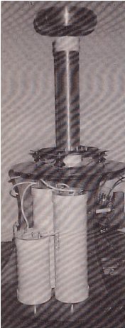
 Roll-Up Design:
The kind of capacitor depicted in Fig. 4 can provide large capacitance in a small size. They are a little trickier to
make than stacked-section type capacitors, so you might want to try a few small prototypes first. The design uses a
layered approach (as shown), and we suggest using only one section as it is difficult to align and wrap multiple
sections. By contrast, a single section several feet long is not too unwieldy.
Aluminum foil works great in these capacitors. You'll find the oven/broiler type, with is heavy-duty foil, far easier
to work with than the plain variety. Polyethylene and Mylar are the most common dielectrics, but you can experiment
with other materials.
Looking at the figure, note the orientation and shape of the foil plated (A) and (C). They can be easily secured to
the dielectric (B) using double-sided Scotch tape. Note also the edge spacing. An outer covering of dielectric (D)
will prevent the finished capacitor from having a "hot" case, which might be a hazard. With those points in mind, lay
the foil out on a smooth sheet of paper, which in turn should be laid out on a smooth, hard surface to prevent
wrinkling. Carefully assemble the four layers as shown in the drawing. Strive to make them flat and smooth.
Warp the capacitor "sandwich" around a non-conductive mandrel or spool--ideally made of plastic or a glass rod
(be careful not to break a glass rod). Try to make the roll straight and free of lumps and wrinkles. When it's all
rolled up, secure it with plenty of tape. The author uses clear package-sealing tape for this. Now secure the
positive foil tab (assuming it's going to be for DC) to the mandrel using tape. Finally, coat the exposed ends with
an insulating product like silicone RTV.
The remaining foil connection tab may be reinforced by rolling it around a small metal dowel. A nail, or a cut-off
piece of 1/8-inch uncoated brazing rod is suggested. Apply glue to hold the assembly tog ether.
Foil tabs can be strengthened by adding "ribs" of adhesive from a hot glue gun. Similarly, the tabs can be made
tear-resistant by applying hot glue where they enter the capacitor.
Note most problems with this design come from particle contaminants that stretch a dielectric thin in spots where
they are trapped by the tightly rolled dielectric. Another trouble is inadequate edge spacing, causing arcing across
the ends. Careful planning and assembly will eliminate both headaches.
High Voltage Safety and Warning Label:
High voltage is considered any value over 500 volts AC or DC. When you attach a capacitor to
high voltage, you are multiplying its hazard many fold. There fore, experimenters must take extra precautions to avoid
painful shocks and possible electrocution. Here are a few guidelines to follow when working with high voltage:
 Label your project in several location with: "Danger, High Voltage" where appropriate. Such
a warning label is provided here for you to copy (See Fig. A). Keep children, pets, and curiosity seekers away from
the apparatus. Cover all bare leads, wires, connection terminals, and possible points of contact with high voltage
putty or a cover fabricated from thick clear plastic.
Label your project in several location with: "Danger, High Voltage" where appropriate. Such
a warning label is provided here for you to copy (See Fig. A). Keep children, pets, and curiosity seekers away from
the apparatus. Cover all bare leads, wires, connection terminals, and possible points of contact with high voltage
putty or a cover fabricated from thick clear plastic.
Work in a dry location. Working in a damp basement of workshop courts disaster. Wear
rubber-soled boots or sneakers. Stand on a thick rubber mat.
Never put your body in a position to become a conductor. Locate your apparatus away from
appliances, metal doors and windows frames, heating ducts, vents, radiators, sinks, or water-pipes. All these items
can become a deadly ground if your body comes between them and high voltage.
Always pull the plug when working on a high voltage circuit unless you must test it. When
testing a live circuit, use the utmost caution. Keep one hand in your pocket. Use clip-on test leads that are rated
twice the voltage of the live circuit. Use a high voltage probe whenever possible--its insulating handle will help
protect you.
Use NE-2 neon lamps to indicate live or stored high voltage. Bleed off the charge on
capacitors with a power resistor before performing adjustments.
Adequate ventilation must be provided for circuits that produce large amount of ozone such as Jacob's Ladders or Tesla Coils.
Copyright and credits:
This article was originally written by Anthony Charlton and the editors of "Electronics Now" and "Popular
Electronics" magazines and published by Gernsback Publishing, 1992(Gernsback Publishing is no longer in business).
Editor's note and Disclaimer:
The device carries lethal high voltage and carelessness can be dangerous to your health. Build and/or use at your own risk.
The Sentex Corporation of Cambridge Ontario, host of "Tony's Website", or Tony van Roon himself, cannot be held liable or
responsible or will accept any type of liability in any event, in case of injury or even death by building and/or using or
misuse of this device or any other high-voltage device posted on this web site. By accessing, reading, printing, or building
the unit in this article you agree to be solely responsible and agree with the above stated disclaimer.
Back to High Voltage Projects Index
Copyright © 2005 - Tony van Roon
Last Updated July 24, 2010