A High-Voltage Pulse Generator
"If you've ever wanted a high-voltage generator to create neat lightning effects, perform
Kirlian photography experiments or play with neon lights, then this one is for you!."
by Dale Hileman, re-written by Tony van Roon
 We will describe a laboratory pulse generator using an auto-ignition coil
and capable of delivering a train of pulses up to 30,000 volts. With a couple of minor circuit and construction
variations, the project is suitable for use as an electric-fence charger, operating at a lower voltage, but capable of
much higher output current.
We will describe a laboratory pulse generator using an auto-ignition coil
and capable of delivering a train of pulses up to 30,000 volts. With a couple of minor circuit and construction
variations, the project is suitable for use as an electric-fence charger, operating at a lower voltage, but capable of
much higher output current.
Applications for a high-voltage spike are numerous: electromagnetic and radio-frequency interference (RFI) studies,
electrostatic-discharge simulation; investigation of insulation breakdown; flammability experiments; strobe effects;
etc. A DC power supply or battery is required, and pulse potential may be varied simply by changing the supply
voltage. With a 12.6-volt input, the ignition-coil model delivers its maximum pulse, but a unique
multivibrator-driver circuit makes operation possible down to a supply voltage as low as 1.5 volts, yielding an output
pulse of only a few hundred volts. Its pulse frequency is set by a front-panel control, with a range from about 0.3Hz
to 20 Hz.
An ignition coil, however, is not well adapted to the fence-charger application since its output resistance is so
high: typically 10,000 ohms. Thus its output pulse is strongly dependent on loading. With a short fence, long sparks
might be struck at risk of igniting brush; while on the other hand, with a long fence, shunting by weeds or by dirt
and moisture may reduce its output voltage below and effective value. Hence for the fence-charger version the rate
prf control must be omitted fro reason of safety.
No-load output of the fence-charger option is typically 4 Kv pk (kilovolts peak), or about half that valuer when
connected to a 1-mile fence. A car battery powers the fence-charger model for about four months before recharging is
needed (at recommended pulsing rate of 20 pulses/minute).
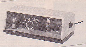
Two lamps mounted on the circuit board and visible through the see-through front panel are important indicators of the
unit's performance.
Precautions:
While a single jolt from an ignition coil is itself rarely traumatic, the resulting-reflex muscle contraction could
have unfortunate consequences. If a continuous train of pulses causes you to involuntarily grasp the high-voltage
conductor, for instance, you might not be able to let go. On the other hand, if proper return circuit is not provided,
an equally distressing shock could be had by contact with the primary circuit. Because the ignition coil is an
autotransformer, the return circuit for the high-voltage pulse includes the power leads. Therefore, one side of the
power supply should, if possible, be Earth grounded. That precaution besides shock by contact with the power leads,
also precludes arcing within the power supply itself as the high-voltage pulse seeks the shortest return path.
Applying that reasoning to the fence-charger option, we can see why a fixed pulse rate is specified, as there is a
strong likelihood of accidental human contact with the fence wire; a rate of 60 pulses per minute or less being
considered safe. Also, since there is a good chance of personal contract with the power leads, a good ground connection
is essential, as with any electric-fence system. For maximum safety, we recommend a battery supply for the
fence-charger system.
If you should happen to reverse the power-supply lease to either project, the current-limitation lamp, a large
automotive bulb easily seen in the photos, lights brightly to warn you . However, the equipments must not be allowed
to remain in this condition for more than a few seconds. Even if you never expect to make this mistake, the lamp
should be included because it limits excessive surge currents that could otherwise occur under some operating
conditions and which could blow the power transistor.
About the Circuit:
As shown in Fig. 1, free-running variable multivibrator Q1 and Q2 drive Darlington power
amplifier Q3, which makes and breaks the primary current to coil T1 as in an auto ignition system. Duty, or "dwell"
is a few milliseconds, and the high-voltage pulse is generated at the end of the period when the circuit is broken and
the field of T1 rapidly collapses trough the winding.
An unconventional multivibrator circuit was developed to provide high saturation currents over a wide range of supply
voltages. In this design both transistors Q1 and Q2 conducting at the same time and both cut off at the same time.
Another unique feature; for safety in the fence-charger application, the circuit is designed to automatically shut
down if driver Q2 should fail to conduct for any reason (fluctuation of powersupply voltage, intermittent connection,
etc.)
Starting with both transistors cut off; C3 is discharging, its negative plate rising toward ground at a rate determined
by various series resistances; while its positive plate is held near zero volts by a relatively low-resistance path
through R6 and R7 and a resistor internal to Q3 across its emitter base junction.
Capacitor C3 discharges fully, and then begins charging in the opposite direction as its negative plate rises above zero
volts.
When Q1 begins conducting, and its collector voltage has dropped far enough to start Q2 conducting also, then a
positive-feedback action is initiated, forcing both transistors into saturation. At the same time, power transistor Q3
is turned on by the current supplied through R7.
Dwell is determined by the time constant R6 x C3. When the charging current of C3 diminishes below the value which will
sustain conduction of Q1, then a regenerative action is again established, this time cutting off all three transistors.
It is that moment the high-voltage pulse is generated.
Further Details:
Capacitors C5 and C6 form a voltage divider which ensures rapid cutoff of Q1; while C6 acts as a bypass to prevent Q1
from being retriggered by pickup of the high-voltage pulse.
Dwell must be long enough to permit the filed around T1 to be fully developed to its steady-state condition under all
anticipated conditions of loading. Although the period is not critical, it may be set for optimum results with a
particular coil or transformer, as described later.
A higher capacitor value at C3 is specified with the fixed-frequency, or fence-charger version, for reasons of safety.
It allows the use of a lower resistance value for R2, reducing the shunting effect of dirt or moisture which might
otherwise cause a significant increase in the repetition rate. That is the reason we specify an axial type for C3,
so that its pads are more widely spaced than they would be with a radial.
 Power Amplifier:
Because the field of T1, as might be supposed, collapses through the primary as well as the secondary, the inductive
"kick" comprises a positive pulse on the collector of Q3. Capacitor C4 is required, as in the conventional auto-ignition
system, to prevent excessively rapid voltage build up. Nevertheless, that reactive voltage reaches several hundred
volts, and we take advantage of it to light neon indicator NE1. Thus, each flash verifies the integrity of the power
amplifier circuit.
If no arc is drawn, the positive pulse on the collector of Q3 is followed by a negative-going excursion. Transistor Q3,
designed for inductive loads, contains a shunt diode which prevents that "backswing" from being applied to the base
through the base-collector junction. That diode also protects Q3 if the power-supply leads are accidentally reversed.
Automotive lamp I1, as we said, limits surge currents occurring as a result of various normal operating conditions, as
well as accidents, such as the reversal of power-supply polarity. Also, it absorbs the energy of the backswing.
The Transformer:
Practically any 12-volt ignition coil having a primary resistance of around 1.5 ohms will work as T1 for the
high-voltage pulse generator, but there's a minor consideration in the choice of a transformer for the fence-charger
project. A common 12-volt 1-amp transformer with 115-volt primary can be used here--hooked up backward of course, so
that the 115-volt winding serves as secondary.
The rapid collapse of its filed when Q3 cuts off, as compared to the relatively slow 60-Hz sinewave for which it is
designed, explains how several thousand volts can be developed across the 115-volt winding (E=L di/dt).
That winding will ty0pically be found to measure 30 to 120 ohms DC, while the 12-volt winding will have a resistance
of around 1 ohm. The author has tried many such transformers for T1, including the Stancor P-8392 and P-8393.
(The latter provides a somewhat bigger jolt although it costs more than the former.) The problem, however, lies in
the breakdown rating of the 115-volt winding.
In most transformers of the species, the winding is rated for breakdown at 1500-volts RMS (corresponding to 2100-volts
pk), with a safety margin that may vary depending on the manufacturer; the Stancor rating proving remarkably
conservative. The author subjected the winding of a P-8393 to 40 million pulses of 4-Kilovolt amplitude without
breakdown. However, he does not guarantee equally good luck in your application.
One way to preclude breakdown with such a transformer is to always operate the fence charger with an appropriate load.
If your fence isn't long enough to load T1 to 2-3 Kv pk, you could reduce the supply voltage: Say, use a 6-volt
battery instead of 12-volt. Or you could substitute for build I1 a type having a lower current rating, and there for
a higher resistance. Either of those approaches, naturally, will somewhat reduce the effectiveness of the unit.
Other Parts:
A type MJE5742 transistor is specified for Q3, rated at 400-volts under heavy inductive load. However, you can at
some risk substitute the cheaper MJE5741 (350-volt rating), depending on T1. In any case, breaking the circuit to an
inductive load is tricky and so if you plan extensive experimentation you should obtains a few spare Q3's.
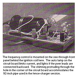
Potentiometer R9 for the variable pulse generator project can be any 2.5 mega-ohm unit from the junk box. If you use
one with a linear taper, though, you will find the control very touchy at the end of the frequency range. The simplest
resolution of that minor inconvenience is to use an ordinary audio-taper potentiometer connected backward; that is
with the high end of the frequency range at the CCW (Counter Clockwise) end.
For reasons already mentioned, the time constant C3XR6 determines dwell, or "on" time. As we have said, dwell is not
critical; but if the capacitor you use for C3 is a low quality part with an excessively high equivalent series
resistance (ESR), the dwell may turn out to be greater than necessary to serve the needs of T1. If in doubt, use a
tantalum type for C3.
The Incandescent Lamp:
We have emphasized the importance of I1, the current-limiting lamp, and have specified a type 1156 automotive bulb.
The merit of an incandescent bulb as a protective device lies in the dependence of its resistance upon the value and
duration of applied current. With a cold resistance of only about 1/2-ohm, the type 1156 degrades performance only
slightly; but in the case of a current surge or accidental short circuit, its resistance quickly rises to a "hot"
value or around 6 ohms, sparing power amplifier Q3 from the devastating requirement of breaking an excessive current
into an inductive load. Nevertheless, there is some leeway in the selection of I1.
For instance, in the lab-generator version where the load has a DC resistance of 1.5 ohms, a lower-resistance bulb
will give a slightly better spark at high frequencies. The author has used a type 1157 bulb here, connecting its two
filaments in parallel, with satisfactory results. On the other hand, as we have indicated above, to prolong the life
of T1 in the fence charger, you may elect a lower-current or higher-resistance bulb. Try the smaller of the two 1157
filaments, alone before experimenting further. After the unit is built feel free to try others.
Parts List for the Fence Charger:

Semiconductors
D1 = No D1 in project; please ignore
D2 = 1N914 silicon diode or similar
Q1 = 2N3904 NPN si transistor or similar
Q2 = 2N3906 PNP si transistor or similar
Q3 = MJE5742, 8A, 400V, NPN darlington power transistor (see text)

Capacitors
C1 = 470uF, 16V electrolytic
C2 = 10uF, 16V electrolytic
C3 = For lab model: 2uF/16V, for Fence Charger: 10uF/16V electrolytic, axial
     (see text)
C4 = 0.27 uF, 400V, film
C5 = 1000pF ceramic disk
C6 = 0.01uF ceramic disk

Resistors
R1,R7 = 100 ohm
   R2 = Selected (see text)
R3,R8 = 10K
   R6 = For lab model: 470 ohms, for Fence Charger: 150 ohms
   R9 = 2.5 megohm pot (see text)

Additional Parts and Materials
 T1 = For lab model: Wells C1819 or similar ignition coil; 1.6 ohm primary,
      10K secondary.  For fence charger: 12V/1A transformer (see text)
NE1 = Neon glow lamp; type NE23 or equivalent
 I1 = 12V/2A, automotive bulb, type 1156 or equivalent

Cabinet or case, PCB, solder lugs of various gauge with internal teeth, cable to
power supply #14 to #18 gauge zip cord or whatever suits, spacers, screws, nuts,
lockwashers, hookup wire, cable ties, solder, etc.

Additional parts for the fence charger only: two battery clips, Mueller #46C or
the like; 1/2-inch pipe, 1-1/2 inch larger nipple, coupling, etc., for
grounding system.
 Circuit Construction:
It is up to you how to house this project and the type of material to buy. You may choose to build either version of
the project in whatever kind of cabinet suits your needs. If you decide to use wire-wrap construction however, the
ground bus and all connections in the power-amplifier circuit should be made with wire no smaller than #24 gauge. In
the author's prototypes, power transistor Q3 stands off the circuit board; but if space limitations permit, a slight
margin of safety is affordable by bolting it down flat so that the circuit board provides a measure of heat
dissipation.
Omit R2 from the circuit board and don't connect the supply conductor to the plus end of T1 until ready to fire up.
Also, leave the secondary leads unconnected for the fence charger.
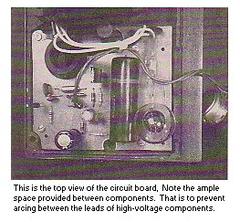
In planning chassis layout, keep high-voltage output conductors well away from the circuit board, especially in the
version using an ignition coil as output transformer. A metallic or otherwise conductive cabinet must be connected to
the circuit common. Since a 30KV pulse is capable of jumping a 1-inch gap, however, you may have some difficulty
finding a feedthrough insulator big enough to handle the high-voltage conductor. One way to meet that requirement
is to use a spark-plug wire, which may be passed through the cabinet wall using only a grommet to prevent chafing. Or
the neck of the coil itself may be used as a feedthrough device, as in the author's mode of construction.
Lab Cabinet Loading:
If you are using the author's recommended cabinet, situate the circuit board in the left end of its bottom. The board
itself can be used as a template for drilling the four mounting holes in the bottom of the cabinet. Mount the
board-assembly on four 7/16-inch metal spacers. The conductive coating in the cabinet bottom may be grounded with a
solder lug placed under one of the screws securing the board to a spacer.
For variable-frequency or lab model, situate the 'rate' control R9 in the clear-plastic front panel. Bring the power
cable into the cabinet through the hole in the bottom rear, using a suitable grommet.
The coil mounts on a platform toward the other end and is secure with a hose clamp. Using the coil called out in the
parts list, some filing of the platform is required. The coil case must be grounded or internal arcing may occur.
Do not depend on casual contact between the coil case and the conductive coating. A grounding connection can be made
by inserting an internal-tooth solder lug between the clamp and oil case. At its base, the coil is stopped by its neck
passing through a hole drilled in the end of the cabinet top. Hence, it's not likely to come loose with normal
handling.
At the free end of spark-pug wire install an alligator clip or other suitable connector. At the other end, first
slide the coil nipple onto the wire, and then install the coil clip.
Important: to preclude arcing, solder the end of the wire to the clip. Push it into the coil neck and
slip the nipple into place. When the top is installed later, the nipple provides a tight seal.
Fence Charger Version:
Construction of the fence-charger version is somewhat simplified by less-stringent needs for insulation and by the more
conventional mounting means for T1. Whatever chassis layout scheme you employ, however, the Earth grounding
requirements described above also apply to this model: If you use a conductive cabinet, it must be connected to the
circuit Earth, and so must the case of T1. Don't forget that a means must be provided to connect that common
to an external ground.
In the author's model of the fence charger, T1 is mounted in the cabinet bottom. To ensure a good connection to the
transformer case, first scrape any varnish or wax from the mounting flanges. Then mount with 1/2-inch metal standoffs
and 8-32 hardware. Use two or three solder lugs as required for various grounding connections.
Mount a ceramic feedthrough insulator in the middle of the platform for fence connecting. The underside of the
platform comprises a recess which, in an outdoor installation, keeps the output end of the insulator clean and dry.
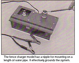
The chimney referred to earlier provides the means for connection to an external ground. A pipe nipple and coupling
are required. First solder a length of hookup wire to the inside of the nipple. A hot iron (say 200 watts) is
required for good wetting. Loosely engage the coupling to the nipple; and passing the wire up through the chimney,
screw the nipple into the opening by turning the coupling. The nipple may engage the coupling as it engages the
chimney. Although the chimney hole is not threaded, the nipple will nevertheless seat securely. Turn the coupling
until it is tight up against the bottom of the cabinet. If desired, apply super glue sparingly around top edge of the
nipple, bonding it permanently to the chimney. Now, if you later need to remove the coupling for any reason, the
nipple will remain in place. Solder other end of the wire to common at the circuit board or at one end of the lugs on
the transformer flanges.
 High-Voltage Attenuator:
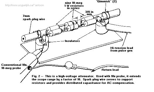
Before proceeding with test and adjustment, you may wish to provide yourself with some means for measuring voltage
pulses beyond the range of the oscilloscope. To that end, you can build a 90-mega-ohm attenuator, as shown in
Fig. 2. When used with a standard 10-mega ohm probe, the device extends the vertical
range of your scope by a factor of ten.
The attenuator consists of nine 10-mega-ohm resistors connected in series. A length of spark-plug wire provides
support for the resistor array and also serves to introduce distributed capacitance for AC equalization. To preclude
arcing, each end should extend an inch or two beyond the terminal.
Once you have commissioned your pulse generator or fence charger, you can fine tune the attenuator by adjusting the
bus-wire gimmicks at either end of the spark-plug wire. That is most easily done by generating a high-voltage pulse
within the range of your oscilloscope (say 1600 volts peak), measuring with only the 10-mega ohm probe; then, trimming
the length of the gimmicks to give the same deflection with the probe connected to the 90-meg attenuator (setting the
sensitivity 10 times higher, of course).
Selecting R2:
We had advised you during construction to omit one connection to the primary of T1 so that you can now select R2
without energizing the power amplifier. Using clip leads, first connect typical value shown in the parts list. Then
connect your 'scope to the junction of R6 and R7, and apply power.
For the lab pulse-generator version, now set the 'RATE' control to maximum frequency and select a value for R2 which
gives a repetition rate of about 20Hz. For the fence-charger model, select a value which gives the desired rate, but
no higher than 60 times per minute. Remember that the slower the rate, the longer between recharging.
Now turn the supply off and add the missing wire to the power-amplifier circuit. In the author's lab-generator
chassis layout, it is necessary to first loosen the coil in order to free the circuit board. If you plan to test the
unit with the circuit board loose, be sure to temporarily replace the lugs grounding the coil case and cabinet.
Place a cardboard sheet under the circuit board to insulate it from accidental contact with the cabinet coating,
etc.. The unit is now ready for a performance test.
Testing:
Connect the high-voltage output to the 90-meg probe or whatever instrument you wish to use to observe the high-voltage
pulse. Turn the power supply on and gradually increase the voltage (adjusting the lab-generator rate as desired),
synchronizing the 'scope to display the largest excursion. (When you don't know exactly what to expect, it's easy to
be fooled into syncing on the backswing or some other minor lobe.)
The unit should start working at a supply voltage of 1.5 to 3 volts, but it will shut itself down if you vary the
voltage too abruptly. If that happens, just tune the power off and then back on again.
At a 12-volt input you should get a pulse of about 20 to 30Kv pk from the lab generator or 3.5 to 5Kv pk from the
fence charger. In the latter version, proceed as follows to decide which secondary lead should be grounded:
1. Turn power off and disconnect scope from both ends. Turn power back on, and
using an insulated tool (to avoid getting zapped), bring each end in turn to the transformer case, leaving the
opposite end free. One will probably draw a small arc and the other won't.
2. Turn power off and ground the one which drew the smaller arc. Connect the
other to the output feedthrough.
3. Reconnect the scope, apply power, observe polarity of output pulse. If you get
a positive pulse, reverse the primary connections. A negative pulse jumps a longer gap from a small object (the fence
wire) to a larger one (the victim) than does a positive pulse (believe it or not).
 If you wish to view the current pulse, temporarily hook 0.1 to 0.2-ohm resistor in series with the negative power-supply
lead, and connect a 'scope across it (being careful to avoid ground loops, as can arise through test connections or
via the power-line safety ground). With fence-charger option, if possible, simulate 1-mile wire by connecting a
0.015-uF, 2000-WVDC capacitor across its output. A rising waveform characteristic of an inductor charging should
be obtained--the abrupt drop at its trailing edge of course representing the cutoff of Q3 and the generation of the
high-voltage pulse.
If you wish to view the current pulse, temporarily hook 0.1 to 0.2-ohm resistor in series with the negative power-supply
lead, and connect a 'scope across it (being careful to avoid ground loops, as can arise through test connections or
via the power-line safety ground). With fence-charger option, if possible, simulate 1-mile wire by connecting a
0.015-uF, 2000-WVDC capacitor across its output. A rising waveform characteristic of an inductor charging should
be obtained--the abrupt drop at its trailing edge of course representing the cutoff of Q3 and the generation of the
high-voltage pulse.
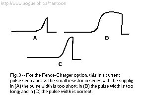
With the lab-generator version, dwell is not critical thanks to the relatively low inductance of the typical
ignition-coil primary. In the fence-charger option, however, primary inductance will probably be much higher and will
vary considerably upon your choice of transformer. 3. shows the current waveform
typical of such a primary. If it ends too soon, that is before the filed has reached its steady-state value (A), then
maximum output capability cannot be attained. If it ends too late (B), then average current consumption is higher
than necessary. To get optimum results (C), adjust the width by changing R6 as needed.
If you know the exact value of the small resistor, given the peak voltage appearing across it you can now calculate
peak current (I=E/R). A typical value is 4 to 6 amps.
Buttoning Up:
Reinstall the circuit board, remembering to replace the lugs which ground the cabinet, pipe coupling, T1, case, etc.,
and to secure the coil. Test the unit once more, then assemble the cabinet.
If you're using the author's recommended cabinet with the pulse-generator option, leave the high-voltage cable and nipple
connected to the coil, passing the other end through the hole in the cabinet top as you bring the top into place.
Slide the front panel up into the cabinet top. Now, close the cabinet by swinging the left side down. Moderate force
is required to push the coil nipple into the hole. Make sure tongues in the cabinet top engage the mating slots in the
bottom, and hold it together with one hand while installing the cabinet hardware with the other. Turn the five bottom
screws snug, but not tight.
Cabinet assembly of the fence-charger version is easier because you don't have to cope with the coil neck or connections
to the front-panel potentiometer. For outdoor use, however, you will have to caulk seams against the weather. Silicone
rubber is good for that purpose because it can later be peeled off if servicing becomes necessary. Arcrylic rubber
makes a better seal, but because it sticks more tenaciously, it makes later disassembly more difficult.
Carefully apply a very thin bead first along the inside edges of the opening in the top front, and install the front
panel. Then, again very carefully and sparingly, apply a bead along the slot in the cabinet bottom; and finally,
assemble the top and bottom. Depending on your skill in the application, there may be some squishing around the
seams. Surplus material around the outsde can be peeled off later, after the sealand has set.
Installation and Operation:
For maximum safety, you should, if feasible, connect one side of the lab-generator power supply to Earth ground. If
not, then be sure to provide a return path for the spark to one of the power-supply leads. Set the "RATE" control to
get the desired rate, and the power-supply voltage to get the desired output potential. If the output is not
excessively loaded, the small in-circuit neon lamp flashes with each pulse. The auto lamp may glow dimly when the
rate is set near its upper limit, but otherwise it should never light during normal operation. It does light brightly
to warn you when the power leads are reversed or if there is an internal short.
If you need one pulse at a time, or bursts of pulses, connect a pushbutton or momentary switch in series with one of
the power-supply leads.
If you have trouble getting lower output voltages, but not higher, the spark-plug cable may have pulled loose. When
that happens, high voltage settings give what appears to be normal performance because the spark path is completer by
jumping within the neck of the coil; while at the lowers voltage settings it appears not to be working at all. If
that difficulty is encountered, pull the cable out, inspect the solder joints, then simply push it back into the coil.
Using the author's cabinet and construction techniques, the fence-charger ground connection is made through the pipe
fittings sticking out of the bottom end of the chimney. An Earth-ground means is provided by an ordinary 1/2-inch
water pipe. The length should be chosen to permit the pipe to be driven at least 3ft deep, but the deeper the better,
depending on estimated conductivity of the soil; with enough pipe rising above ground to place the unit at a
comfortable viewing level. Thus a pipe of at least 7ft is required. A more effective ground can be had by adding
salt to the soil.
Temporarily screw a pipe cap onto top end so as to protect the threads during hammering operation. Pound it into
the ground, remove the cap, and screw the fence-charger assembly onto the end. Connect the fence and battery to the
unit.
The neon lamp flashes with each pulse to assure you that everything is working okay, except in absolute darkness,
since a few photons of light are necessary to prime the neon. That apparent drawback, however, has the
definite earmarks of an advantage because when it's pitch black the unit cannot call itself to the attention of an interloper.
Copyright and credits:
This article originally was written by Dale Hileman and the editors of "Electronics Now" and "Popular
Electronics" magazines and published by Gernsback Publishing, 1992 (Gernsback Publishing is no longer in business).
Re-written and re-drawn by Tony van Roon.
Editor's note and Disclaimer:
The device carries lethal high voltage and carelessness can be dangerous to your health. Build and/or use at your own risk.
The Sentex Corporation of Cambridge Ontario, host of "Tony's Website", or Tony van Roon himself, cannot be held liable or
responsible or will accept any type of liability in any event, in case of injury or even death by building and/or using or
misuse of this device or any other high-voltage device posted on this web site. By accessing, reading, printing, or building
the unit in this article you agree to be solely responsible and agree with the above stated disclaimer.
Back to: High Voltage Projects Index
Copyright © 2005 - Tony van Roon
Last Updated July 24, 2010