"In this article we explore the mysteries of Kirlian Photography and show you how you can
investigate the phenomenon yourself!"
by Tony van Roon
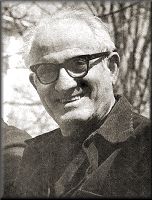 Semymon Davidovitch Kirlian was born on February 25 of 1898 in the city of
Krasnodar, in the South of Russia. Semymon Kirlian could have been inspired and to have taken interest in the study of
unusual and natural phenomena by a visit by Nikola Tesla to Yekaterinodar in 1917 where he gave a conference just
before the 1917 revolution. Kirlian attended this conference and went away deeply impressed.
Semymon Davidovitch Kirlian was born on February 25 of 1898 in the city of
Krasnodar, in the South of Russia. Semymon Kirlian could have been inspired and to have taken interest in the study of
unusual and natural phenomena by a visit by Nikola Tesla to Yekaterinodar in 1917 where he gave a conference just
before the 1917 revolution. Kirlian attended this conference and went away deeply impressed.
Semymon Kirlian used his experiences along with trial and error to verify the correctness of his own ideas, and coupled
with his stubborn and laborious method of work, proved successful with the creation of a device for photography and
visual observation by means of high frequency, high-voltage, low-current electricity.
Kirlian was more interested in technical matters such as equipment or investigating characteristics of metals and
non-conductors. Valentina Kirlian, on the other hand, was more interested in the study of life processes.
Then In 1939, while repairing medical equipment used in d�Arsonval electrotherapy, Kirlian discovered that the
electrical discharge between a vitrified electrode and particles of human skin changed color. Trying to discover the
cause of this, he photographed the electric charge without the use of a conventional camera, that is, exposing the
film directly to the current.
This experiment led to the invention of a system of high-frequency electrical photography. During the next ten years
of work at home and in the workshop where he repaired medical and other types of equipment, Semymon and Valentina
Kirlian were repeatedly successful in photographing by means of high-frequency currents.
They devised a non-standard but simple apparatus, and in 1949 they received an "Author's Certificate" (Soviet patent
for "A Method of Photographing by means of High-Frequency Currents").
Their simple device and the photographic method was completely revolutionary and unprecedented. Semymon and Valentina
subsequently received hundred from letters from scientists and research institutes from all the parts from the Soviet
Union.
Kirlian began his work in electro-photography in 1939. Now, over 65 years later, that work is still the source of
much speculation and controversy. That's because it has been claimed that Kirlian was able to use auras that surrounds
the objects in his electro-photographs to detect illness in plants and animals before any other outward symptoms were
visible.
Whether those claims are true or not, they sparked a good deal of interest in the field of electro-photography; so much
so that electro-photography is today commonly called Kirlian photography.
What is it?
In Kirlian photography, a variable frequency high-voltage source is used to produce images on photographic film. It
does so without the benefit of a camera, lenses, or light, so it can, in some ways, be likened to X-ray photography.
The resulting photograph is a recording of the cold electron emission created by the high-voltage source. How the
emission is modified by the subject or object used in making the photographs is the focal point of Kirlian photography.
 Many of the theories used to explain the effect read like excerpts from a science-fiction novel. One theory put forth
by Dr. F. Cope, who was investigating the Kirlian aura at the Bio-Chemistry Laboratory at the Naval Air Development
Center, in Warminster PA, felt that all substances and, in particular, living organic matter, contains and are
surrounded by what can best be described as a matter energy field. When a high-voltage charge is introduced into
that field, it becomes or behaves like a superconductive plasma. The laws of physics that pertain to such a plasma
are complex, involving an extended form of Einstein's Theory of Relativity. It is possible that the aura recorded
around objects may be a physical manifestation of that matter field.
Many of the theories used to explain the effect read like excerpts from a science-fiction novel. One theory put forth
by Dr. F. Cope, who was investigating the Kirlian aura at the Bio-Chemistry Laboratory at the Naval Air Development
Center, in Warminster PA, felt that all substances and, in particular, living organic matter, contains and are
surrounded by what can best be described as a matter energy field. When a high-voltage charge is introduced into
that field, it becomes or behaves like a superconductive plasma. The laws of physics that pertain to such a plasma
are complex, involving an extended form of Einstein's Theory of Relativity. It is possible that the aura recorded
around objects may be a physical manifestation of that matter field.
Unfortunately, when Dr. Cope died, the research unit disbanded. While Dr. Cope was alive, though, he was one of the
few scientists with the courage to do research into what is considered, at best, a fringe science.
It is that fringe-science category that impedes research into the filed, in addition to quickly become associated with
quacks, phychics, and pseudo-scientists that permeate the field. It is easy to see that any scientist wanting to
seriously investigate electro-photography is going to be met with serious opposition, and could possibly lose their
standing in the scientific community.
But is the opposition justified? Is it possible that the procedure has no merit whatsoever? I don't think so and, to
make my point, allow me to draw a few analogies. We analyze light from stars to determine their composition, and their
doppler shift to determine speed. Those two facts have created a foundation upon which modern cosmology in the last
century stands. We typically perform spectrographic and colormetric analysis to determine a compound's composition.
It is therefore my belief that the Kirlian effect may provide a tool with which we can probe nature.
 Despite the opposition to electro-photographic research, Kirlian images have been used experimentally, as a diagnostic
tool, in medicine, and for non-destructive testing of materials in engineering. One interesting aspect of electro-photography
is that, while all objects appear to produce an electro-photographic aura, the aura of inanimate objects appears constant
over time, while living creatures give off an aura that is time varying. In humans, emotional stress, illness, and
alcohol of drugs all appear to have an effect on the aura.
Despite the opposition to electro-photographic research, Kirlian images have been used experimentally, as a diagnostic
tool, in medicine, and for non-destructive testing of materials in engineering. One interesting aspect of electro-photography
is that, while all objects appear to produce an electro-photographic aura, the aura of inanimate objects appears constant
over time, while living creatures give off an aura that is time varying. In humans, emotional stress, illness, and
alcohol of drugs all appear to have an effect on the aura.
One of the U.S. government's studies in the area involved using the Kirlian aura to ascertain the physical and mental
health of military personnel, and to determine their level of fatigue. That was done by measuring the diameter of the
aura or corona, at the fingertip. At the end of the test, the results were analyzed and two statistically valid
conclusions could be drawn. One was that the corona of those suffering physical stress (fatigue, etc.) had coronas that
were smaller than the test average.
It may appear obvious than those test results could be due to the dilation or constriction of the blood vessels. Another
study proves that assumption incorrect. Compounds given to individuals to dilate or constrict blood vessels
do not produce a statistical difference in the corona diameter, according to a report.
While the results of the tests were interesting, there is still not enough data to hail Kirlian photography as a
"fool-proof" diagnostic test. Although other similar tests have been reported, the results have been incomplete. For
instance, in one study, the fingertip coronas of 120 adult humans were photographed. Of the sample, 20% had a corona
diameter that was markedly below the average. It was later determined that 50% of that 20% suffered from some sort of
medical problem.
There are several obvious flaws with that study. For one, no reports was made on the health of the 80% whose coronal
diameter was not reduced; it would have been informative to know what percent of those whose corona diameters were
decreased and show had no ascertainable medical problems. It would have been interesting to see how many of them
developed some kind of difficulty, and in what time frame following the experiment.
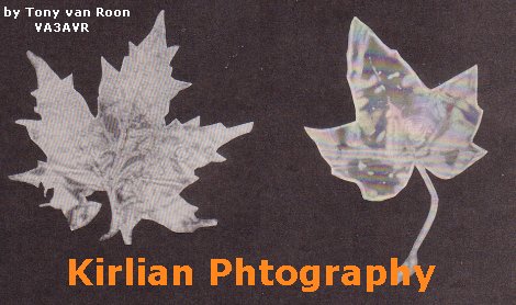
The most dramatic experiment in Kirlian photography, and one that has garnered the most attention, is the so-called
phantom-leaf phenomenon. In that experiment, a small part (approximately 2% to 10% of the total surface area) of a
leaf is cut off. Electro-photographs subsequently taken will sometimes show the energy pattern or aura of the missing
section. The reason for that is unknown, and it is the subject of much speculation, and although the effect is
exceptionally rare, it has been demonstrated enough times by different people to prove its existence. One important
fact must be kept in mind if you wish to attempt to replicate the phantom-leaf effect. The leaf must still be attached
to the parent plant when shooting the photograph.
 Making your own:
There are probably quite a few doubters still out there. To those we offer the following challenge: Why not build
your own Kirlian-photography unit and prove or disprove the existence of the effects yourself? The worst-case scenario
is that your will build a device that takes exceptional, beautiful, and toxic photographs of the most-common items
lying around. In the balance of this article we will present a simple set up that will allow you to do just that.
Although the equipment is not on par with that used in research labs, it is still more than sufficient to provide
startling results. The color photographs that accompany this article showing the Kirlian aura of some common leaves,
were produced using the apparatus as described.
The circuit for the setup is shown in Fig. 1. The heart of the circuit is a 555 timer in astable mode whose frequency
is controlled by a double-ganged pot. The output of the timer is fed into Darling-transistor Q1. The Darlington
transistor controls two TO-3 power transistors that switch the current on and off to a three-terminal automotive
ignition coil, L1.
Construction is straight-forward, and the circuit is simple enough that a PC board is not required--although you can
use one if you wish. Not that the transistors can get hot, so they should be heat sinked. The only other point that
merits special mention is that a plastic chassis is essential, to provide adequate shock protection from the coil and
is also essential to properly mount the exposure plate on top of the chassis (see Fig. 2).
Figure 3 shows the internal mounting of the components. The ignition coil is epoxied or glued to one side of the
chassis so that the high-voltage terminal is lying underneath the copper-clad board on top. A single-sided
copper-clad board measuring 4x5 inches is mounted on top of the unit (see photo), copper side down. Before gluing
the board in place, solder a wire to the copper side, and then drill a hole through the top of the chassis for the
high-voltage terminal on the ignition coil.
Three-terminal ignition coils can be obtained from any automotive supplier or an automotive junk yard. Just about
any 12-volt, three terminal coil will work.
The most-costly component in the assembly is the plastic chassis. The overall dimensions are 3.25 inches high, 6.25
inches deep, and 8.0 inches wide. If you wish, the chassis, as well as wired and tested units, can be purchased from
the supplier mentioned in the Parts List.
The setup used in making a Kirlian photograph is shown in Fig. 4. The film is placed on the board mounted to the top
of the unit, and the specimen to be "photographed" is inanimate, such as a leaf or a piece of metal, it should be
grounded for best results. Any earth ground that you can connect a ware to will work fine. In any event, the
specimen is placed between two sheets of thin (0.010-inch) transparent plastic, and the "sandwich" is then placed on
the film.
Never ground a living creature, including yourself. Doing so can subject the "specimen" to a very nasty shock.
When dealing with living creatures, take special care to prevent any contact with a ground.
 One note about the ignition coils high voltage terminal: To the uninitiated (read: unexperienced), the location of that
terminal may not be apparent at first glance. It is located within the tube-like protuberance at the top of the
housing. When the coil is used in it's normal application, a spark-plug wire is placed in the opening at the top of
the tube so that it makes contact with the terminal inside; the wire is held in place by friction. For our application,
the lead from the copper-clad board must make good contact with the high-voltage terminal.
One note about the ignition coils high voltage terminal: To the uninitiated (read: unexperienced), the location of that
terminal may not be apparent at first glance. It is located within the tube-like protuberance at the top of the
housing. When the coil is used in it's normal application, a spark-plug wire is placed in the opening at the top of
the tube so that it makes contact with the terminal inside; the wire is held in place by friction. For our application,
the lead from the copper-clad board must make good contact with the high-voltage terminal.
You will note from Fig. 1, that the circuit uses two on/off switches, S1 and S2. Switch S1 is the unit's main power
switch; when it is in the 'ON' position, power is supplied to the neon lamp, NE1, and the circuit is placed in
standby mode. The neon lamp does more than give a visual indication of the state of the unit. Since we are working
with photographic film, the circuit must be used in a relatively dark, light-tight room. Obviously, that can present
problems in using the unit. IF the controls are clustered around the lamp (as shown in Fig. 5), the lamps gives off
just enough light to make identification of the controls possible in a dark room without adversely affecting the
Kodalith film. When your use color film, you should block the light from the film. Switch S2, the discharge switch,
is a 'normally-open' momentary type.
It is used to control the balance of the circuit.
To make a Kirlian photograph, turn on the unit using S1, turn off the lights, place the film and specimen on the top
plate as discussed previously, and make the exposure using S2. As a guideline, start with an exposure time of 10 to
15 seconds. It is likely that you will do a lot of trial-and-error experimentation with both the exposure time and
frequency (which is adjusted using R1) before you will obtain satisfactory results.
The original author (John Iovine) has had good results with two types of film: Kodak 6118 Ektachrome and Kodalith 2556.
The Ektachrome film will give you spectacular color transparencies, such as the one accompanying this article.
However, it can be difficult to work with and to develop. Unless you have a photographic darkroom and are equipped
for developing that type of film, you will probably want to take it to your local photo-developing store.
Kodalith 2556 ortho film type-3 is a high-contrast, black-and-white graphics-art film that may be familiar to those who
make their own PC boards. The results are less spectacular, as shown in Fig. 6, but that film's light requirements are
less exacting (a photographic safelight or the red neon lamp on the unit can be left on when handling the film), and
the processing is much simpler, requiring just three basic chemicals. The author found the right exposure using the
Kodalith first, and Ektachrome for the final exposure.
Parts List:
All resistors are 1/4-watt, 5%, unless otherwise noted
   R1 = 25K double-ganged potentiometer
R2-R5 = 2K2
   R6 = 1K
   R7 = 5 ohms, 10 to 20 watts

Capacitors
   C1 = 2200uF, 35-volts, electrolytic
   C2 = 0.1uF
   C3 = 0.01uF, 2000-volts

Semiconductors
  IC1 = 555 timer (not the cmos type)
   Q1 = TIP120, NPN darlington transistor
Q2,Q3 = 2N3055 NPN transistor
   D1 = 2.5A/1000-volt silicon diode
  BR1 = 4A/50-PIV bridge rectifier

Other Components
NE1 = Neon lamp assembly, red
 T1 = 120volt/12volt, 3A transformer
 S1 = SPST pushbutton switch
 S2 = momentary N.O. pushbutton
 L1 = 3 terminal, 12volt automotive ignition coil (see text)

Miscellaneous:
Chassis, knobs, 4x5-inch single sided copper clad pcb plate, line cord, etc.

Note: Complete assembled and tested Kirlian unit available for $187.50 from
Images Co., P.O. Box 313, Jamaica, NY 11419.  Plastic chassis $30.00 each plus
shipping and handling.
Tony's Note: This article is from 1992 and as such probably no longer available
from the address listed above. I have not checked if it still exists or if it does, the price will have gone up.
Suggested Reading:
Kirlian Photography by John Iovine (2000). Published by Images Publishing Co., ISBN: 0-9677017-0-8.
"A Hands-on Guide"
The Unseen Self: Kirlian Photography Explained by Brian Snellgrove. Publisher CW Daniel. ISBN: 0-8520727-7-5
Copyright and credits:
The original article was written by John Iovine and the editors of "Electronics Now" and "Popular Electronics"
magazines and published by Gernsback Publishing, 1992(Gernsback Publishing is no longer in business).
Re-written, modifications, and drawings by Tony van Roon.
Editor's note and Disclaimer: The device carries lethal high voltage and
carelessness can be dangerous to your health. Build and/or use at your own risk. The Sentex Corporation of Cambridge
Ontario, host of "Tony's Website", or Tony van Roon himself, cannot be held liable or responsible or will accept any
type of liability in any event, in case of injury or even death by building and/or using or misuse of this device or
any other high-voltage device posted on this web site. By accessing, reading, printing, or building the unit in this
article you agree to be solely responsible and agree with the above stated disclaimer.
Back to High Voltage Projects Index
Copyright © 2005 - Tony van Roon
Last Updated July 24, 2010