Build this Stun Gun
"Man's fascination with high voltages began with the first caveman
who was terrified by a bolt of lightning. In more recent times, electronics experimenters and hobbyists have found
the Tesla Coil and the Van de Graaff generator equally fascinating. In this article we'll show you how to build a
hand-held high-voltage generator that is capable of producing 75,000 volts at a power level as high as 25,000 watts.
The Stun Gun can be used to demonstrate high voltage discharge and as a weapon of self defense (law permitting in your
area). Before building one, however, you should read and pay very close attention to the warning in the accompanying
text box, as well as to the description of physiological effects that follows."
by Robert Grossblatt and Robert Iannini
Reproduced with permission from Radio Electronics Magazine
 Click here to READ THIS FIRST!
Physiological Effects:
So that you may understand the danger inherent in the stun gun, let's discuss the physiological effects first. When
a high voltage is discharged on the surface of the skin, the current produced travels through the nervous system by
exciting single cells and the myeline sheaths that enclose them. When that current reaches a synapse connected to a
muscle, it causes the muscle to contract violently and possibly to go into spasms.
the longer contact with the high voltage is maintained, the more muscles will be affected. If the high voltage
maintains contract with the skin long enough to cause muscle spasms, it may take ten of fifteen minutes before the
brain is able to re-establish control over the nerve and muscular systems.
How much power is required to cause such spasms? That is not an easy question to answer because, although it is
relatively easy to make precise measurements of the power produced by a high-voltage device, it is difficult to rate
the human body's susceptibility to shock accurately. Some obvious factors include age and diseases such as epilepsy.
But the bottom line is simple: The only one who fools around with a stun gun is a fool!
The amount of energy a device delivers is actually the amount of power delivered in a given period of time. For our
purposes, it makes sense to talk about energy in joules (watt-seconds). Using a fresh 9.8-volt NiCad battery, the
stun gun is capable of delivering peak power pulses of 25,000 watts. Actually, pulses start out at peak power and
then decay exponentially. The length of the decay time depends on the components used in the circuit, the ambient
temperature, the battery's capacity, and positioning of the output contacts with respect to each other.
Assuming that the decay rate is purely exponential, the stun gun can produce about 0.5 joules of energy, provided
that the battery is fully charged. Let's put that number in perspective.
Both the Underwriter's Laboratory (in Bulletin no. 14) and the U.S. Consumer Product Safety Commission state that
ventricular fibrillation (heart attack) can be caused in humans by applying 10 joules of energy. Since the stun gun
only generates about half a joule, you might think that a device that produces only one twentieth of the critical
amount has more-than-adequate margin of safety. Don't bet on it. A brief contact with the stun-gun's
discharge hurts a great deal, but it takes only five seconds of continuous discharge to immobilize someone completely.
Let's compare the stun gun's output with a similar device, called a Taser gun, which appeared on the market a while
back (and now used by several police forces). You may have seen a film demonstrating just how effective the Taser
could be as a deterrent. A foolhardy volunteer was paid an enormous sum of money to have the Taser fired at him.
No matter how big, strong, (and stupid) the person was, as soon as the Taser's "darts" hit him, he would collapse to
the ground and go into uncontrollable convulsions.
The energy produced by the Taser is only 0.3 joules--about 60% of what our stun gun produces! Even so, the Taser has
been officially classified as a firearm by the Bureau of Tobacco and Firearms because it shoots its electrode "darts"
through the air. Even though our stun gun doesn't operate that way, the Taser puts out considerably less energy than
the stun gun. Keep those facts and figures in mind when you assemble and use the device.
 How it Works:
The
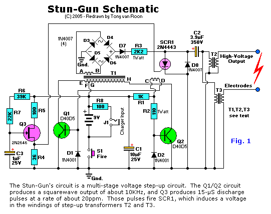
schematic diagram of the stun gun is shown in Fig. 1. Basically, it's a multi-stage power supply arranged so that each
succeeding stage multiplies the voltage produced by the preceding stage. The final stage of the circuit feeds two
oppositely-phased transformers that produce extremely high voltage pulses. If that description sounds familiar,
you've probably studied capacitive-discharge ignition systems--the stun gun works on the same principles.
The first section of the power supply is a switcher composed of Q1, Q2, and the primary windings (connected to leads
E, F, G, and H) of T1. When Fire Switch S1 is closed, R1 unbalances the circuit and that causes it to start
oscillating. Since base current is provided by a separate winding of T1 (connected to leads C and D), the two
transistors are driven out of phase with each other, and that keeps the circuit oscillating. Resistor R2 limits
base drive to a safe value, and diodes D1 and D2 are steering diodes that switch base current from one transistor to
the other. Oscillation occurs at a frequency of about 10 kHz.
The switching action of the first stage generates and AC voltage in T1's high-voltage secondary (leads A nd B). The
amount of voltage depends on the battery used, but a battery of seven to nine volts should produce 250 to 300 volts
across T1's secondary.
That voltage is rectified by the full-wave bridge composed of diodes D3 - D6. Capacitor C2 charges through D7 at a
rate that is controlled by R3
The value of capacitor C2 affects the output of the stun gun. The greater the capacitance, the more energy that can
be stored, so the more powerful the discharge will be. A larger capacitor gives bigger sparks, but requires more
charging time, and that gives it a lower discharge rate. On the other hand, a smaller capacitor gives smaller sparks,
but a faster discharge rate. If you wish to experiment with different values for C2, try 3.9µF (as shown in
Fig. 1), 7.8µF, and 1.95µF. Those values were arrived at by using one 3.9µF capacitor alone, two
of the same in series, and two in parallel.
 Meanwhile, UJT Q3 produces 15-µs pulses at a rate of about 20ppm. That rate is controlled by C3 and the series
combination of R6 and R7. When a pulse arrives at the gate of SCR1, it fires and discharges C2. That induces a
high-voltage pulse in the primary windings of T2 to T3, whose primaries must be wired out of phase with each other.
The result is a ringing wave of AC whose negative component then reaches around and forces the SCR to turn off.
When the next pulse from Q3 arrives, the cycle repeats.
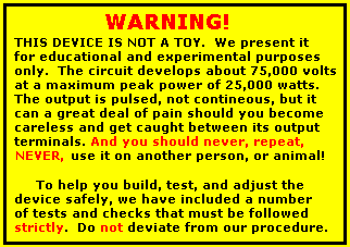
The outputs of the stun gun appear across the secondaries of T2 and T3. The hot leads of those transformers connect
to the output electrodes, which should be held securely in position about two inches apart, and which should be
insulated from each other and from the environment with high-voltage potting compound.
Batteries:
The stun gun can be powered with almost any battery that can supply at least 7 volts at 1 amp. A NiCad or NiMh
battery would be a good choice; R8 and J1 will allow the battery be recharged without removing it from the case.
The higher the battery's voltage, the higher the stun gun's output voltage. Most 9 volt NiCads actually have maximum
fully-charged output of only 7.5 volts. However, batteries that deliver 9.8 volts when fully charged are available
from several sources.
 Construction:
Keep in mind the fact that the stun gun produces dangerously high voltages, and don't approach the construction of
the stun gun with the same nonchalant with which you might build a light dimmer.
The circuit can be built on a PC board or on perfboard. If you build the circuit on a perfboard,
follow our parts layout closely; otherwise you may have problems with arcing.
Due to the critical nature of the three transformers, we are NOT providing details of winding them. They are(were)
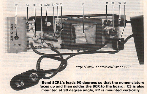
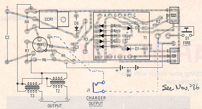
available from the source in the parts list. Referring to the parts-placement diagram in Fig. 2, and the photos in
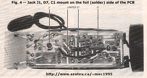
Fig. 3 and 4, mount all components except C2, T1, T2, and T3 on you board. Note that several components mount on the
foil side of the PC board: C1, D7, and J1. DO not install those parts yet either.
After all components (except those mentioned earlier) are installed, check your work very carefully, especially D1-D6,
R1, and R3, because T1 will be installed above them, and there will be no chance to correct errors later. After
you're absolutely sure that they're installed correctly, install T1 with the black mark on the windings mounted
toward C2.
Parts List:
All resistors 1/4-watt, 5%, unless otherwise noted
   R1 = 1K
   R2 = 110 ohms, 1 watt
   R3 = 2K2, 1 watt
   R4 = 36 ohms
R5,R8 = 100 ohms
   R6 = 39K
   R7 = 22K

Capacitors
C1 = 10uF/25V, electrolytic
C2 = 3.9uF/350V, electrolytic
C3 = 1uF/25V, electrolytic

Semiconductors
D1,D2 = 1N4001, 50-volt rectifier
D3-D8 = 1N4007, 1000-volt rectifier
Q1,Q2 = D40D5, power transistor
   Q3 = 2N2646, UJT
 SCR1 = 2N4443

Other Components
   B1 = 9V NiCad battery
   S1 = SPST momentary pushbutton switch
   T1 = 12 to 400 volts saturable-core transformer, See text
T2,T3 = 50 KiloVolt pulse transformer, 0.32 joules, 400 primary. See text

Note: The following components *used* to be available from Information
      Unlimited, P.O. Box 716, Amherst, NH 03031: T1, T2&T3(or potted), C2,
      PCB, Case, Charger, 9.8V battery, or a complete kit ($40 in 1992).
We do NOT supply any parts whatsoever for this project!
Foil-side Components:
One of J1's tabs shares a hole on the PC board with resistor R8, which should be mounted already. Solder the tab of
J1 that corresponds to the tip (not the barrel) of an inserted plug to the indicated pad. Then mount C1 and D7.
last, solder a 1-3/4 inch piece of 18-gauge wire to the barrel pin of J1, and connect the opposite end of that wire
to the appropriate pad beneath S1, the FIRE switch.
Preliminary Check-out:
WARNING: While measuring voltages and currents, keep you face, hands, and all metallic
objects away from the high-voltage end of the stun gun. If you want to prod a component, use a NON-conductive rod
such as a plastic TV alignment tool. High voltage behaves very differently than low voltage. Any material that
retains moisture can serve as a discharge path. THAT INCLUDES WOOD! Also, never work on or use the unit when your
hands are wet.
Connect a voltmeter (set to a 1000-volt DC range) to ground and to the output of the D3-D6 diode bridge. Then power
up the circuit using either a freshly-charged battery or an external supply capable of delivering 9.8 volts at 1 amp.
If everything is working properly, you should measure about 400-volts DC at the output of the bridge when you press
S1. And please, PLEASE be careful. Being careless or not alert can be a painful
shocking experience!
If you don't measure that voltage, connect an oscilloscope to the collector of Q1 or Q2. You should see a square-wave
with a period of about 100µs. If that waveform is not present, the switching circuit is not operating correctly.
Remove power and check your wiring again. Do NOT debug the
circuit with a battery connected!
Resistor R6 controls the rate at which the UJT (Q3) discharges, and R3 controls the rate at which C2 charges. You can
experiment with the values of those components if you are not satisfied with the circuit's high-voltage output. R3
can vary from 2K2 to 4K7. You can also experiment with the value of C2.
After the circuit is operating correctly, attach J1 to the board with high-voltage potting compound or RTV. And
before you mount the circuit in a case, make sure there's no arcing on the PC board. If there is, you can stop it
with a liberal application of RTV, paraffin, or epoxy.
Conclusion:
The stun gun's discharge is very impressive. The spark is highly visible and each discharge produces a sharp,
resounding crack. The circuit can teach you much about voltage-multiplying circuits and power supply design.
But don't ever forget that the stun gun is not a toy. It can cause much damage to both you and others. Never
leave it lying around where children, pets, or anyone unfamiliar with how to use it can handle it. It's a good
idea to remove the battery before storing the stun gun. Above all: be careful!
R-E
Editor's note and Disclaimer: The Stun Gun is an illegal firearm in Canada, except for
use by specialty forces, law enforcement or special permits. Except for laboratory experimentation, and under close
supervision, having a Stun-Gun in your possession is the same as having an illegal gun or a gun without the proper
FAC permits. It is presented here for educational and experimental purposes only as part of our High-Voltage
Projects. We do NOT supply parts or materials of any kind for this project.
Again, depending on your State or Province, it may be illegal to possess, have in possession, or built this device.
Build and/or use at your own risk. The Sentex Corporation in Cambridge Ontario, host of "Tony's Website", or
Tony van Roon himself, cannot be held liable or responsible or will accept any type of liability in any event, in case
of injury or even death by building and/or using or misuse of this lethal device or any other high-voltage
device posted on this web site.
By accessing, reading and/or printing this article you agree to be solely responsible via the above terms/disclaimer.
As stated previously, we do NOT supply any parts whatsoever for this project.
Copyright and Credits:
The original article was written by Robert Grossblatt, and Robert Iannini. Reproduced from Radio Electronics
Magazine, September 1986, by permission of Gernsback Publishing, Inc. (Gernsback Publishing is out of business since
January 2000). Document updates & modifications, all diagrams, PCB/Layout redrawn by Tony van Roon.
Re-posting or taking graphics in any way or form of this project is expressly prohibited by international
copyright © laws and enforced by International Law Enforcement.
Back to High Voltage Projects Index
Page Copyright ©2002 Tony van Roon

 Click here to READ THIS FIRST!
 How it Works:
 Meanwhile, UJT Q3 produces 15-µs pulses at a rate of about 20ppm. That rate is controlled by C3 and the series
combination of R6 and R7. When a pulse arrives at the gate of SCR1, it fires and discharges C2. That induces a
high-voltage pulse in the primary windings of T2 to T3, whose primaries must be wired out of phase with each other.
The result is a ringing wave of AC whose negative component then reaches around and forces the SCR to turn off.
When the next pulse from Q3 arrives, the cycle repeats.
 Construction:
