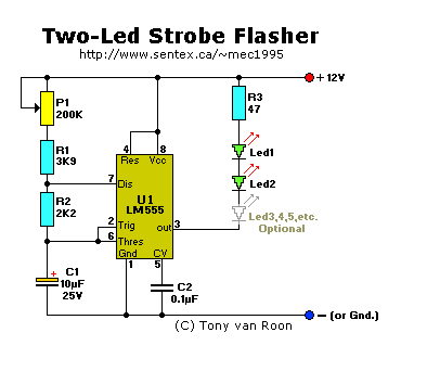
Parts List:
R1 = 3K9            C1 = 10uF-25V, electrolytic
R2 = 2K2            C2 = 0.1uF-50V, ceramic (100nF)
R3 = 47 ohm         U1 = LM555, timer/oscillator
P1 = 200K         Leds = White (or your color), 5mm, ultra-bright
Description:
This little circuit provides a surprisingly spectacular bright strobe flash which is adjustable with P1, the 200K trimmer potentiometer. P1, R1, R2,
and C1 provide the flashrate. R1 sets the upper flashrate. The flashrate for the above circuit was measured at 12Vdc. If the supply voltage is
steady or regulated, the flashrate is very stable.
Capacitor C2 on pin 5 of the IC is to filter off noise when used in motorized vehicles. For battery power it can be eliminated. Resistor R3, 47 Ohm,
is there to protect the Leds for burn-out. Depending on your application and power source, increase or decrease the value of R3. Like, for a 9V power
source decrease the value to 22-33 ohms or so. For a 15V power sourse increase the value to 680-1000 ohms.
The duty-cycle is about perfect at 50% so will give a nice strobe when adjusted with P1 to a fast flash. I experimented with several color Leds and
basically they all strobe very bright especially the white ones. Current draw of this circuit (measured with two leds in series) is 21mA with white
leds, 26mA with Green leds, 40mA for the yellow, 38mA for the Red, and 26mA using only 1 Blue led. Again, this is the *total* circuit amps, not the
led amps. The strobe effect with the white leds was very impressive.
I use this circuit as anti-collision strobe in the wingtips of my radio control airplane with a 9-volt power source. I first carved out a nice
little pocket of about 2 inches in each of the wingtips. Then I glued in reflectors (taken from a $1 camera from the recycle store) and then
installed the the two leds and wired up the to the strobe circuits. I used one circuit in each of the wing tips rather than using long wires between
the leds. The copper in the wires for the length needed is much havier than using two separate circuits. Unless of course you're concerned with the
possible uneven flash between the wingtips? I'm not. Anyways, the circuit itself weighs almost nothing so lending itself for use in radio control
very nicely. I also installed a red led on the tailvin tip of my helicopter. Gives a very nice effect. Many other r/c applications are there for
the taking. Or use it as a brakelight strobe for your motorcycle, etc.
You can use several leds in series if you need more strobe-effect. I have used as many as 10 without problems on my motorcycle to make sure I'd be
seen, especially at dark. Works great!
Back to Circuits Page
Copyright © Tony van Roon
Last updated: June 29, 2010

