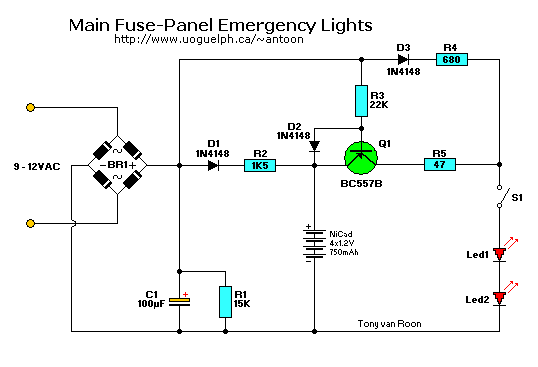
The area around the Main Electrical Panel is usual pretty dark, especially if it is located in the basement. That's
during daylight hours. At night everything is dark during a powerfailure, or tripped circuit breaker, fuse, etc..
This circuit provides ample time to fix the problem.
A bell transformer is used to provide the AC power to the circuit. It can be anything from about 6 to 12VAC and this
circuit can be used without modifications for this AC range. Just watch the working voltage of the electrolytic
capacitor C1. A 25V type will work but to keep if safe go for a 50V or better.
When the main power is interrupted for any reason, the circuit is fed via the 4 NiCads which provide 750mAh at about
5 volt DC. The LED's are of the ultra-bright type, 20,000mCd or better.
Parts List:
Resistors are 1/4 Watt, 5%
R1 = 15K
R2 = 1K5
R3 = 22K
R4 = 680 ohm
R5 = 47 ohm

Capacitors:
C1 = 100uF/25V, electrolytic

Semiconductors:
   Q1 = BC557B, general purpose PNP transistor
D1-D3 = 1N4148
 Leds = Ultra High Brightness, blue/white, 20.000 mCd or higher
  BR1 = B80C1000 (80V/1A) Bridge Rectifier

Miscellaneous:
S1 - Main Fuse panel door switch (optional), or regular on/off switch.
4 NiCad batteries, 1.2V/750mAh
Transistor Q1:
The BC557B can be replaced with a NTE159, but Rotate device 180� to conform with original lead configuration.
Copyright and Credits:
Source: "Elektuur, Halfgeleider Gids", 1998. Copyright © Elektuur Magazine, The
Netherlands.
Document updates & modifications, all diagrams, Layout, editing, © Copyright by
Tony van Roon.
Re-posting or taking graphics in any way or form of this project is expressly prohibited by international copyright
laws.
Back to Circuits page
Copyright © 1995 -- Tony van Roon
Last updated June 19, 2006

