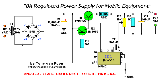
Parts List:
Resistors are 1/4W, carbon, 5% tolerance (or better).

 R1 = 200 ohm                          IC1 = uA723
 R2 = 10K, potentiometer             Q1,Q2 = 2N3055, NPN power, TO-3
 R3 = 1K                               BR1 = Bridge Rectifier or 4 Diodes,
RSC = 0.065 ohm                                 10A, 100PIV
 C1 = 10,000uF/50V electrolytic         T1 = Transformer, 117VAC-20VAC/10Amp
 C2 = 500pF, ceramic
 C3 = 100uF/25V electrolytic
Description:
A 10,000uF/50V electrolytic capacitor completes the filtering of the 28.8V. Yep, C1 is a real clunker. You can use larger if you like, just watch it when you power up. Without a 'power-up' delay circuit of sorts it will probably blow-up the 723 if the capacitor (C1) is too-large.
The DC voltage coming from BR1 is fed to the collectors of the in "Darlington" connected 2N3055 NPN power transistors. The base drive for the pairs transistors is coming from pin 10 of the uA723 through a 200 ohm current limiting resistor, R1.
The reference terminal, pin 6, is tied directly to the non-inverting input of the error amp (pin 5), providing 7.15V for comparison.
Inverting input to the error-amplifier on pin 4 is fed from the center arm of a 10K potentiometer connected across the output of the supply. This control is set for the desired output voltage of 13.8V. Compensation of the error-amplifier is accomplished with a 500pF capacitor connected between pin 13 and 4 of the 723.
If the power supply should exceed 8A or develop a short-circuit, the 723 regulator will bias the transistors to 'cutoff' and the output voltage will drop to near zero until the short circuit condition is corrected.
Circuit courtesy Texas Instruments.