Precision Power Supply
© 1986 Doug Bedrosian and 2010 Tony van Roon
"This Precision Power Supply is a nice addition on your workbench as primary, or in my case, a
supplementary power supply. With zero to 40V and 2A with adjustable current limiting it will surely gets lots of use on your bench. On average the
most amperage for a power supply someone needs is around two or three amps. The sensitivity for current limiting is fully adjustable. Have fun
building!"
Introduction:
Test instruments are considered to be some of the most useful tools available when constructing a project. They are also considered to be the most
expensive tools one could buy. For instance, a power supply of any quality and usefulness can range from several hundred dollars to several thousand
dollars. The alternative to buying a power supply is to build one. The power supply in this article has a voltage range from 0 to 40V and a current
range from 0 to 2 amps with current limiting set by the user. The quality of the supply is determined by the time and care the builder takes while
constructing it.
How It Works:
The power supply is best understood when divided into separate parts.
The first parts to look at are the two power supply sections. The output supply section consists of XFMR1, Br1, C1, and C2. They supply the
appropriate voltage and current required at the output. The IC supply consists of XFMR2, Br2, and C3. The two power supply sections must be separate
from each other because a floating ground is required for IC1.
The next section is the voltage control. RV1 and R2 determine the operating point of a constant current source out of pin 3 of IC1. By varying RV1
the maximum output voltage will be set. Pins 8 and 9 are inputs to a high gain differential amplifier contained in IC1. By adjusting potentiometer P1
the voltage at pin 8 will vary; this will cause the voltage at the output to change until it is equal to the voltage at pin 8. Due to the high gain of
the differential amplifier the voltage at pins 8 and 9 will always remain equal.
The current control section is next. Pin 12 of IC1 is an internal voltage reference, used with RV2 and R3 they set the maximum output current. RV2 is
adjusted to limit the maximum output current to 2 amps. The inputs to the high gain differential amplifier of the current control section are pins 10
and 11 of IC1. By adjusting potentiometer P2 the maximum voltage across R5 and R6 before current limiting are set. This voltage is proportional to
the output current, therefore the maximum output current will be set.
Constant current/constant voltage is the next section to look at. The outputs from the voltage and current high gain differential amplifiers are fed
through an OR gate. The output that is chosen by the OR gate will then be the output of the IC, which is at pin 5. This causes the supply to
switch between the constant voltage or constant current mode.
The next sections to describe are the compensation and protection circuits. C4 is used for internal compensation of IC1. D4 and D5 prevent the input
voltage to the high gain differential amplifier from exceeding 0.7V. D2 and D7 protect the supply from damage that may be caused when an external
power supply is connected.
The output section is next, pin 5 is the output of IC1. This drives Q1 which inturn drives Q2. The main power dissipated by the supply will be by Q2,
this is why an appropriate sized heatsink is required.
Construction of the Printed Circuit Board:
The printed circuit board is highly recommended to be used when constructing the power supply, as it will save time and reduce the risk of wiring
errors. It is also recommended that the PCB be assembled in the order that the instructions are given.
The first step is to check the PCB for any oxidation on the copper traces. If the copper looks oxidized, use some fine steel wool to remove it. Now
JP1 can be installed and soldered in. Next is the 14 pin IC socket, making sure that the pin 1 marking on the the socket is aligned with the pin 1
marking on the PCB. Now Br1 and Br2 are soldered in place. Special care should be taken so that the positives on Br1 and Br2 are matched with the
positives on the PCB. C1, C2, and C3 are next. Again care should be taken so that the positives on the capacitors are matched with to the positives
on the PCB.
Before anymore parts are installed the power supply sections of the board should be tested. Temporarily wire the 36 volt transformer to the
appropriate section on the PCB. With the transformer on, measure the voltage across C1 or C2. It should be approximately 50V, plus or minus 5V.
Now the 36 volt transformer can be disconnected and the 17 volt transformer can be connected to the appropriate section on the PCB.
With the transformer on, measure the voltage at pin 14 and pin 7 of the IC socket; pin 14 being positive, and pin 7 being negative. The voltage should
be between 22 volts and 28 volts. If the voltage across pins 14 and 7 is out of this range the power supply will not work!
It should be noted that the transformer(s) for the 17 and 36 volt supplies must be electrically isolated from each other. This can be achieved by
using two separate transformers (which is recommended) on one transformer with two completely isolated windings. If this is not the case the power
supply with fail to work.
With both power supply sections on the board functioning, construction on the board may continue. The seven diodes can be soldered in place; and care
should be taken when installing them, so they are oriented correctly on the board. Next the eight resistors can be installed, then the four
trimpots. The board has been laid out for two types of trimpots, the choice is left up to the builder as to which are used. Now the remaining
capacitors can be installed, Q1 is next to be installed, for proper orientation of Q1 refer to Fig. 1.
BEFORE IC1 can be inserted, discharge all electrolytic capacitors to prevent damage to the CMOS IC MC1466L. C9, the 22nF polyester
capacitor is not mounted on the printed circuit board, it is soldered over the output jacks.
With the board now complete, refer to the External Wiring Section for the remaining connection to the board.
External Wiring:
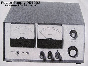
The construction and choice of cabinet is left up to the builder. The enclosure used in this article was the Hammond 1458 series. This makes a
compact, professional looking power supply. Once the enclosure is completed the wiring of the supply may begin.
The first step is to wire up the power cord with the power switch and fuse. If you're using a metal enclosure, you *MUST* use a 3-wire power cord with
ground wire. The power cord's wire colors are 'black', 'brown'(or white), and 'green'. The black wire is the so called 'hot' wire or phase, the brown
or white wire is neutral or '0'. The green wire (sometimes green with a yellow stripe) goes to ground, which is a clean connection to your metal
enclosure. When you have connected the ground of the power cord to the enclosure, measure it with your multimeter for continuity. One probe of the
meter goes to the ground plug of the power cord, the other probe goes to the enclosure. You want to measure on another spot in the enclosure than
where you connected the ground wire. The idea here is to make sure you have an almost 'zero' ohm reading between the green wire and the metal enclosure.
Do *NOT* connect the ground wire to the center-wire (CT) on the primary of the transformer or anywhere else on the transformer. Leave this wire floating.
I mention this just in case. I have seen the weirdest (and most dangerous) scenarios in regards to ground wire connections in all sorts of power
supplies, so I just want to make sure everything is done correctly with this power supply. The Green Jack on the front panel is your 'chassis' ground.
It is sometimes needed with battery operated circuits and test equipment such as an oscilloscope.
Okay, on with it. Refer to the schematic diagram. As shown, the original author (Doug Bedrosian), wired one side of the power cord to the fuse and
the other to the switch. I don't like that method of wiring to the 115VAC at all. In my opinion dangerous. An inexperienced builder could hookup the
neutral instead of the hot to the switch which ment if the powersupply is 'switched off' the hot side of the 115VAC would always be present on the
circuitry. Not the way they do it in Europe and not my way either.
I would recommend a DPDT switch (Double Pole Double Terminal) which switches both neutral and hot at the same time. A
1uF/400V polyester capacitor (or MOV's) over this switch will filter off any possible sparks from the switch (see diagram in the main schematic).
 Now the on/off indicator. The original schematic has an LED wired with a resistor to the primary 115VAC. I don't like that either; very dangerous
by my standards. However you do it, take my advice and connect the on/off indicator somewhere after the bridge rectifier where the voltage is at a
safe DC level. It doesn't matter which bridge rectifier. Using a bright led is my choice. I used an on/off switch which contains a led, and can be
either red, green, or orange. I choose the red led. Now, how to calculate the series resistor for the led? I drew the led in the 17VAC section
because there simply was more drawing space but you can do it either way. The 17VAC becomes 24.48VDC (17v x 1.44pp) after being rectified by
the bridge rectifier. The voltage of the led is a standard 1.5V at 18mA current. 24.48 x 0.018 = 1360 ohms. The nearest value up is 1500 ohm or 1K5.
Now the on/off indicator. The original schematic has an LED wired with a resistor to the primary 115VAC. I don't like that either; very dangerous
by my standards. However you do it, take my advice and connect the on/off indicator somewhere after the bridge rectifier where the voltage is at a
safe DC level. It doesn't matter which bridge rectifier. Using a bright led is my choice. I used an on/off switch which contains a led, and can be
either red, green, or orange. I choose the red led. Now, how to calculate the series resistor for the led? I drew the led in the 17VAC section
because there simply was more drawing space but you can do it either way. The 17VAC becomes 24.48VDC (17v x 1.44pp) after being rectified by
the bridge rectifier. The voltage of the led is a standard 1.5V at 18mA current. 24.48 x 0.018 = 1360 ohms. The nearest value up is 1500 ohm or 1K5.
Now the secondary of the transformers, the wires with the 17VAC and the 36VAC, should be wired to the PCB.
The two meters plus the voltage and current controls can be wired to the PCB. Refer to the wiring diagram for proper connections. Next Q2
should be mounted to a heatsink, the heatsink used should be of appropriate size in order for proper cooling of Q2 under high loads. The transistor
should be mounted using an insulating (mica) wafer coated on both sides with silicon compound. The insulating wafer is used to electrically isolate
the transistor from the heatsink and the compound is used to improve the heat transfer from the transistor to the heatsink. Make sure to use the nylon
screw-insulators when mounting the transistor. When you're done, test the heatsink and transistor for continuity. One probe goes to the case of the
transistor and the other probe goes to a 'shiny' spot of the heatsink. *NO* continuity or connection is allowed. If there is, then the problem is
likely because of the way the transistor is mounted. You need two nylon screw-insulators.
You can check here to see how the insulators are actually used (look at the 2N3772 picture):
http://www.sentex.ca/~mec1995/circ/ps3010/ps3010b.html.
When wiring Q2 to the PCB a minimum of 18 gauge wire is recommended. The output terminals are wired to the PCB next. Again, a minimum of 18 gauge
wire is recommended.
The construction of this power supply is now complete. Refer to the Testing and Adjustment section for proper setup of this power supply.
Parts List:
Resistors:
All resistors are 1/4W unless otherwise indicated
R1 = 1K2 RV1,RV2 = 5K
R2 = 7K5 RV3 = 500 ohm
R3 = 15K RV4 = 100K
R4 = 160 Ohm P1 = 50K, Bourns, 10-turn potentiometer
R5,R6 = 0.22 ohm, 5W P2 = 500 ohm potentiometer
R7 = 10K, 1W
R8 = 180K
R9 = 330K, 1W
Note: R5 and R6 are "wire-wound" types
Capacitors:
C1,C2 = 2200uF, 100V, electrolytic
C3 = 1500uF, 50V, electrolytic
C4,C7 = 0.1uF, 25V, ceramic
C5 = 10pF, 25V, ceramic
C6 = 240pF, 25V, ceramic
C8 = 100uF, 100V, electrolytic
C9 = 22nF (0.022uF), 100V, polyester or similar
Semiconductors:
D1-D8 = 1N4007
Br1 = 6A, 200V Bridge Rectifier, KBPC102 or similar
Br2 = 1A, 50V Bridge Rectifier, MDA100A or similar
Q1 = TIP31C, NPN power transistor, TO-220 (NTE184)
Q2 = 2N6385, NPN power transistor, TO-3 (NTE245)
IC1 = MC1466L, precision regulator IC, 14-pin DIL (no known substitute)
Led1 = LED, your choice on/off indicator
Miscellaneous:
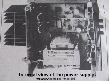
T1/T2 = Transformer with two windings; 17VAC/300mA, and 36VAC/3A (JS-92-096)
(or two separate transformers, but will take more space)
S1 = SPDT, Power on-off switch (the Led1 for on/off can be part of S1)
J1,J2,J3 = Binding posts, one Red (+), one Black (-), one green (Gnd.)
Knobs = 2 knobs for voltage and current potentiometers
Other:
Heatsink for transistors Q1 and Q2
2 meters 250uA (microAmp) each
Cabinet or enclosure Hammond 1458 series.
 Testing and Adjustments:
With the PCB and wiring completed, the power supply is ready for testing. The first step is to set all trimpots to the midway position. Not turn the
voltage and current controls to the midway position as well. Power may now be applied to the board. If all is working properly there should be a
voltage reading at the volt meter. If the needle of the volt meter is going in the wrong direction reverse the wires at the meter. If there is no
voltage reading at the meter check to see if the current control is set at zero, if so, turn it to the midway position. If the supply still appears to
not function properly, use an external voltmeter to measure the voltage at he output terminals. If there is a voltage then a problem with the
supply's voltmeter is likely. If there is no voltage at the output or if there is a very small amount, measure the voltage across pins 7 and 14 of
IC1. If it is not between 22 and 28 volts the power supply will not function. If the proper voltage is across pin 7 and 14 and the supply is not
functioning properly then it is recommended that the PCB and wiring be thoroughly inspected for flaws. It is also possible when the IC was inserted
in the IC socket one of the pins was bend underneath the IC. Or, also a possibility, the IC itself is defective. Replace the IC only when everything
else checks out okay.
With the supply working properly it can now be adjusted for use. The first step is to set the maximum output voltage. With an external voltmeter
connected across the output terminals, the voltage control should now be turned for maximum output. Now adjust RV1 on the PCB until the external
voltmeter reads 40 volts. Now adjust RV4 so the power supply's voltmeter also reads 40 volt.
Next the maximum current should be set; an external ampmeter capable of handling 2 amps is connected across the output jacks. With this ampmeter
connected, the output will be driving close to a dead short. Now set the current control for maximum current; with the power supply on, adjust RV2
until the external ampmeter read 2 amps. Once this is completed RV3 should be adjusted so the current meter of the power supply reads also 2 amps.
Now the meters on the power supply should be checked for accuracy. First, with the power supply switched OFF, check to see if the needle on the
meters need 'zero-ing', meaning, if the needle is not exactly showing '0' but is off a little bit, you can adjust this needle mechanically with the
plastic screw on the meter panel. Let's proceed. Using an external voltmeter (multimeter) connected across the output jacks, adjust the voltage
control for different readings on the supply's voltmeter. If the readings of the two voltmeters are inconsistent then the voltmeter of the supply
should be readjusted using the procedure already given. With an external amp-meter (or ampere-meter) connected across the output jacks, adjust the
current for different readings on the supply's amp-meter. If the two meters are inconsistent the amp-meter of the supply should be readjusted using
the steps given previously.
Assuming everything is adjusted properly, the power supply is now ready for use on your workbench. Although the supply's 2 amp is not a whole lot, it
is sufficient for most of your electronics designs and hobby projects. And yes, if you wish to extend the current a couple more amps, it can be done.
Use:
The power supply is very easy to use. There are only two controls, one being the voltage, the other being the current, therefore the maximum output
current will be set.
By adjusting the voltage control the output voltage varies. By adjusting the current control the maximum amount of current which the supply will
generate is set. By understanding the function of each control the user will be able to operate the power supply for maximum performance in each
situation. You can use it to charge your battery packs too. You adjust the power supply to the maximum current the battery pack is allowed to have,
generally 1/10th of the total current. If the NiCad battery pack indicates '2100mA' you charge it at 1/10th which is 210mA. The voltage initially
may be a lot higher than indicated on the battery, but that is the effect of Ohm's Law and nothing to worry about. When the battery gets
charged, the current will drop gradually until the battery has a full charge. I do recommend monitoring the process closely. A charge of about 9 to
15 hours or so, depending on if you're charging NiCad or NiMH, is quite normal.
Copyright and Credits:
The original copyright holder of the "Precision Power Supply" article is Doug Bedrosian and published in "Electronics Today" of October 1986.
Article is edited with new information, artwork, and drawings, by Tony van Roon, 2010.
Back to Circuits
Copyright ©(C) 1986 by Doug Bedrosian, (C) 2010 by Tony van Roon
Last Updated: September 08, 2010