

ScanMate
"Add this easy project to your regular scanner or DX'ing apparatus and never miss action again.
Or use this system to check a range of frequencies for band activity when you're not there. I use it to check a range
of 'secret' frequencies overnight when I'm sleeping. Works for me."
by Tony van Roon
Introduction:
What exactly is 'ScanMate'? Read on. It never seems to fail. You wake up in the morning, turn on the radio news,
and there it is: A major fire across town, a drug bust in the local park, police chases, or an airliner forced to
make an emergency landing along the highway. Such events always seem to happen just after you have turned off your
scanner and gone to bed, or left the house.
Some of the hottest action to come over the air waves for months, and you missed it....that is, until ScanMate!
With ScanMate connected between your scanner and a tape recorder (via the recorder's microphone or auxiliary input
and its remote start jack), you will never have to worry about missing any of the action again.
ScanMate is similar to several of the available commercial units, but offers greater flexibility. The ScanMate unit
has a 'level' control that allows it to be used successfully with any type of scanner--portable or base
unit--regardless of its output-amplifier configuration. It also provides control over the length of time the
recorder continues to run after the transmission ceases. Also included in the circuit is a switch that allows you to
select either automatic or manual operation.
When ScanMate is set to the auto-mode, the recorder's motor operates only during transmissions. In the manual-mode,
the motor is activated whenever any of the recorder's functions (play, rewind, etc.) is selected. That allows all
the interconnection cables to remain in place when you decide to rewind and listed to the tape. A speaker in/out
switch is provided to allow monitoring (via the circuit's build-in speaker) while recording. In addition, ScanMate
provides both microphone and line-level outputs, so that even the least-sophisticated recorders can be used.
How It Works:
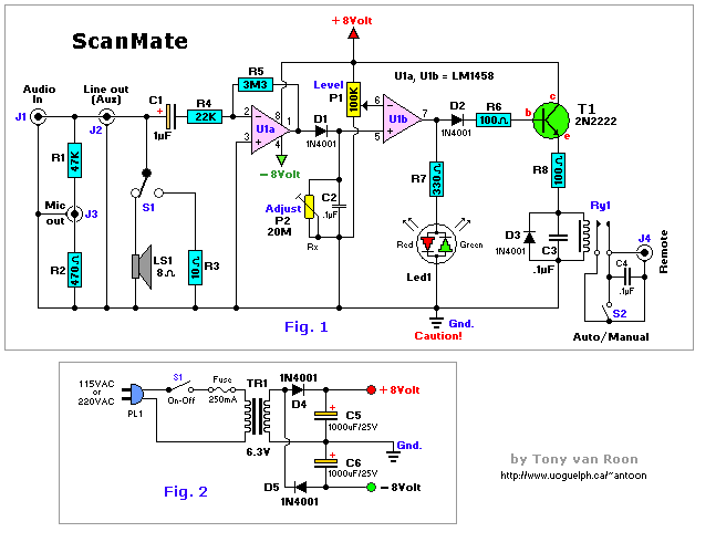
Figure 1 is the schematic diagram of the ScanMate circuit. Audio coming from the scanner's earphone or speaker jack is
fed to the circuit via J1. Jack J2, which is wired parallel with jack J1, provides a line-level output for input to
the recorder via its auxiliary input jack. The signal is also fed through a voltage divider, consisting of resistors
R1 and R2, which attenuate the signal for the mic-out jack J3.
Switch S1 is used to switch speaker LS1 in and out of the circuit. In the 'out' position, a 10-ohm resistor, R3, is
switched into the circuit in place of the speaker's 8-ohm impedance, providing a fairly constant lead for the
scanner's output. Capacitor C1 blocks any DC voltage that might be present. The signal is then fed to the inverting
input of U1a (1/2 of a LM1458 dual op-amp), the gain of which is set to about 150 by the R4/R5 combination. The
output of U1a at pin 1 is rectified by diode D1. The peak voltage is fed across C2 to the non-inverting input of U1b,
which is configured as a voltage comparator. When the voltage at pin 5 is higher than that set by P1
(the level/sensitivity control) at pin 6, the output of U1b swings to near the positive supply rail, lighting the
green half of LED1, a bi-color Light Emitting Diode.
Resistor R7 limits the current to LED1. The high at U1b's output (pin 7) also turns on T1 which, in turn, activates
a reed relay, Ry1, causing its contacts to close. The contacts of the relay act as the tape-recorder's motor on/off
switch. When the voltage at pin 5 of U1b is lower than that at pin 6, its output swings close to the negative supply
rail, illuminating the red half of LED1, and at the same time turning off T1 and Ry1, as well as the tape recorder's
motor.
The discharge rate of C2, combined with the setting of P1, determines the time the recorder runs after the last
transmission. With an LM1458 Op-Amp, and its relatively low input impedance a C2 value of 0.1uF provides an ideal
discharge rate. However, if a high input impedance op-amp is used, such as one with JFET inputs, C2's value should
be increased to around 5uF (4.7uF is ok) and the value of P2 should be adjusted to near 10-megohms. Some
experimentation with the setting of P2 -- which value should be between 5 and 30 megohms -- may be necessary to
achieve optimum performance. I only used the adjustable potmeter (P2) to find the optimum setting and then measured
that resistance and replaced the pot with an appropriate value of a resistor (Rx). Works.
Diode D3 and capacitor C3 are used to shunt any harmful spikes produced by the relay's coil away from T1. Switch S2
is the 'Manual/Auto' select switch. When S2 is closed, it acts like the closed contacts of the relay, turning on the
tape-recorder motor.
The circuit is powered from a dual 8-volt power supply, (see Fig. 2) consisting of a handful inexpensive components.
The AC line voltage is fed through S3 (the on/off switch) and a Fuse of 0.25 Amp (250mA) to power transformer TR1,
which reduces the 117V line to 6.3 volts. That voltage is then full-wave rectified by D4 and D5, and filtered by
electrolytic capacitors C4 and C5, to provide a suitable power source for the circuit.
Parts List:
    R1 = 47K                   C1 = 1uF/16V            S1 = on-on, SPDT Switch
 R2 = 470 ohm         C2,C3,C4 = 0.1uF (ceramic)    S2 = on-off, SPST Switch
 R3 = 10 ohm             C5,C6 = 1000uF/25V         S3 = on-off, SPST Switch (115VAC)
 R4 = 22K          D1,D2,D3,D4 = 1N4001            Ry1 = Reed Relay, 5V-1A
 R5 = 3M3                   T1 = 2N2222            TR1 = Transformer, 12.6V CT, PC-Mount
 R6 = 100 ohm               U1 = LM1458                  Socket for U1 (8-pin)
 R7 = 330 ohm              LS1 = Speaker, 8-ohm    >>Radio Shack<< or Tandy part #'s
 R8 = 100 ohm         J1,J2,J3 = Jacks, 3mm*
 P1 = 100K, Lin             J4 = Jack, 2mm*        Notes: 3M3 (R5) same as 3.3M
 P2 = 20M 10-turn         LED1 = Bicolor LED*             µ = micro or u
 (Rx) optional, see text

A KIT for this powersupply is available here: [ScanMate KIT]
Construction:
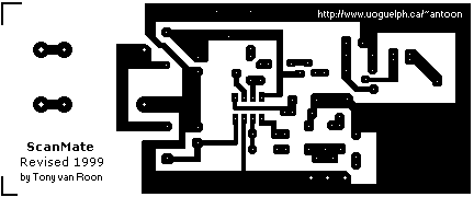
There is nothing critical about the circuit's layout, and its okay to use perfboard, but using the printed circuit
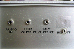
board pattern shown in Fig. 3 helps to simplify matters. Jacks J1 to J4 should be of whatever type matches the inputs
to your scanner and tape recorder. In my case, the mic/aux/audio jacks are the standard 3mm and the remote jack 2mm
in the ScanMate prototype.
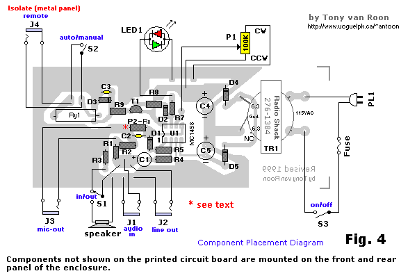
Fig. 4 is the parts-placement diagram for ScanMate's printed circuit board. Note that several components for the
circuit are mounted off-board on the front and rear panel of the project enclosure. After positioning the off-board
components, run short lengths of hookup wire from the appropriate points on the board to those components.
 Turning to the bi-colored LED used in the circuit; if a similar unit cannot be found, the two-color unit can be
replace by two discrete LED's. Of course, it will be necessary to supply an appropriate dropping resistor for each
unit; or if you decide to hook them up back-to-back (duplicating the unit's schematic symbol), you may have to play
with the value of the dropping resistor.
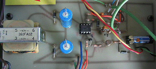
I used a Radio Shack 12.6 volt, center-tapped (ct) transformer in the power-supply of his prototype. I was unable to
obtain the 300mA version so saddled for the 500mA type which meant modifying the PCB a bit since the transformer is
larger in size. The output of the transformer is taken from its center tap, thereby providing 6.3 volts AC for the
rectifier circuit. If you have difficulty in locating a similar unit, you might consider using a 12-volt transformer
(with sufficient current rating), along with a 7808 and a 7908 (positive and negative, respectively), 8-volt, three
terminal regulators. If you choose to go that route, be sure not to overlook the filter capacitors.
I have not experimented with an DC-type adapter but don't see why that should not work. If you have a 8 or 9 volt
DC adapter of at least 300mA or better, try it. Saves the cost of the power supply parts + powercord in Fig. 2.
As for the enclosure itself, there are a couple of things to watch for should you decide to use a metal cabinet
to house the project (as in my case). A lot of tape recorders with positive grounds or other unusual circuitry react
violently to having either side of their remote start switches grounded. To prevent that problem, the remote start
jack (J4) should be covered with heat shrink, or whatever, to keep the contacts completely isolated from ScanMate's
other circuitry. You will most likely hear tremendous 'hum' if the remote jack is improperly isolated from the metal
panel. (if, of course, you use a case with metal front and rear panels). You may have noticed that, unlike the other
jacks, the remote jack is not connected directly to ground.
TR1 is a pc-mountable 12.6volt/300mA Center Tapped transformer. I purchased mine at Radio Shack: #276-1385. Some
modifications were required to the PCB-layout to make the transformer fit nicely. Just in case you don't have a lot
of experience with electronics and you're wondering why the schematic shows 6.3V and the parts list 12.6V. The
transformer is a so-called 'center-tapped' model which means 6.3V - 0 - 6.3V. Either side of the '0' provides 6.3V.
The '0' is the center-tap (Gnd.), or CT for short. We only use one side of the transformer with the center tap.
CAUTION: Because of the +8 and -8 volts, the above circuit ONLY uses the ground coming from the center-tap of TR1!
In addition, because the circuit derives power from a 117-volt AC outlet, make certain that the board is mounted in
its enclosure on standoffs to prevent the board from coming in contact with the cabinet.
Making a neat cutout for speakers is always a problem, if you're not handy with mechanical equipment, but can be
easily solved by putting the opening at the bottom of the cabinet, where imperfections won't be noticed. I solved the
problem by drilling 3 millimeter holes in a half star pattern. Looks really good. Anyone can drill a couple of holes
right?
Check my Radio Shack data sheet for partnumbers; makes things easier when you
visit the Radio Shack/Tandy store.
Just in case you have any problems finding some of the parts: You can replace the 2N2222 for a NTE123A (not AP), a
2N2219, BC107, or a TUN type as specified in Elektuur (Elektor), or try something else (if it works it works right?).
By the way, a 2N2222 is the same as the MPS2222A type from Radio Shack. If you can't find the LM or MC1458, use the
NTE778A, or the 276-038 model from Tandy/Radio Shack; they are all pin-for-pin compatible as far as I know. The
1N4001 diodes can be substituted with a NTE116 or the #276-1101 model from Radio Shack. An 1N4002 or 1N4003 model will
work just fine also, they just have a higher PIV. Transformer TR1 is available from Radio Shack as the #273-1384
6.3v/300mA. The general term for this type transformer is "filement" transformer because of the 6.3V. But use what's
available in your area.

Using The ScanMate:
After connecting ScanMate, a scanner, and a tape recorder together, flip the speaker switch (S1) to the 'on' position
and turn the 'level/sensitivity' potentiometer (P1) fully counter-clock-wise. Next, find a busy channel on the
scanner and put the tape unit into the record mode. LED1 should be red, meaning the tape is stopped. Slowly turn the
P1 potentiometer clockwise until the bi-colored led turns green. At that point, your tape recorder should be running,
recording everything coming over the scanner. Turn back a little back until the red led comes on again and the tape
recorder stops. Monitor the whole thing for a bit and re-adjust if necessary.
Now switch to a silent channel and check how long it takes for ScanMate to shut off the recorder. If the delay isn't
right, turning the 'Level' potentiometer clockwise (up to a certain extend), will increase the time before shut-off,
turning it counterclockwise shortens the delay. Again, keep in mind that the level of delay is limited by the values
of P1 and C2.
Copyright and Credits:
The original project was written by Tim Goebel under the name "Auto Scan". Reproduced from Popular Electronics,
August 1989, by permission of Gernsback Publishing, Inc., 1996. Revised, updated, and modified. All diagrams,
Printed-Circuit Board and Layout redrawn by Tony van Roon. Gernsback Publishing, Inc., no longer exist.
Re-posting or taking graphics in any way or form of this project is expressibly prohibited by international
copyright © laws.
Back to Circuits page
Copyright ©1996--Tony van Roon


 Turning to the bi-colored LED used in the circuit; if a similar unit cannot be found, the two-color unit can be
replace by two discrete LED's. Of course, it will be necessary to supply an appropriate dropping resistor for each
unit; or if you decide to hook them up back-to-back (duplicating the unit's schematic symbol), you may have to play
with the value of the dropping resistor.
