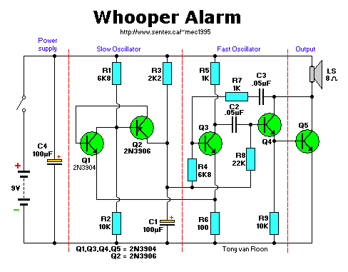
Parts List:
      R1,R4 = 6K8               C1,C4 = 100uF,16V electrolytic
      R2,R9 = 10K               C2,C3 = 0.05uF, ceramic
         R3 = 2K2
      R5,R7 = 1K                   B1 = 9V Alkaline Battery
         R6 = 100 ohm           SPKR1 = Loudspeaker, 8 ohm
         R8 = 22K                  S1 = SPST switch
Q1,Q3,Q4,Q5 = 2N3904
         Q2 = 2N3906

A complete KIT plus Printed Circuit Board will be available soon.
Note that the printed circuit board is only available with the kit.
Whooper Alarm:
Exchange R8 for a higher pitch. Experiment with R8, C1, or combination thereoff.
Copyright:
This article is © EKI (Electronics Kits International, Inc. (no longer in business))
Destroyer Whooper using transistors
Back to Circuits Page
Copyright © Tony van Roon

