Capacitor Tutorial

   © by Tony van Roon


What Exactly Is A Capacitor?

     Like my other tutorials, lets start with a bit of interesting history first to understand where the 'capacitor' or condensor came from and how it was developed and then work our way up to our century.

Pieter van Musschenbroek In 1745 a new physics and mathematics professor at the University of Leyden (spelled Leiden in modern Dutch), Pieter van Musschenbroek (1692 - 1791) and his assistants Allmand and Cunaeus from the Netherlands invented the 'capacitor' (electro-static charge or capacitance actually) but did not know it at first. His condenser was called the 'Leyden Jar' (pronounced: LY'duhn) and named so by Abbe Nollet. This Leyden jar consisted of a narrow-necked glass jar coated over part of its inner and outer surfaces with a conductive metallic substance; a conducting rod or wire passes through as insulating stopper (cork) in the neck of the jar and contacts the inner foil layer, which is separated from the outer layer by the glass wall. The Leyden jar was one of the first devices used to store an electric charge. If the inner layers of foil and outer layers of foil are then connected by a conductor, their opposite charges will cause a spark that discharges the jar. Actually, van Musschenbroek's very first 'condenser' was nothing more than a beer glass!

Franklin's Kite Experiment By modern standards, the Leyden jar is cumbersome and inefficient. It is rarely used except in exciting laboratory demonstrations of capacitance, and exiting they are! Benjamin Franklin was acquainted with the Leyden Jar experiments also so he decided to test his ideas that 'charge' could also be caused by thunder and lightning. Franklin tested his theories, in Philadelphia in June 1752, via his now famous 'Electrical Fluid Theory' to prove that lightning was an electrical phenomenon. What he did was fly a kite which had a metal tip. The kite was tied with wet conducting thin hemp cord and at the end he attached a metal key to which a non-conducting silk string was attached which he held in his hand; when he held his knuckles near the key he could draw sparks from it. Although his experiment was completed successfully and the results as he had calculated before, the next couple people after him who tried the hazardous experiment were killed by lightning strikes. I guess Franklin was extremely lucky with his hazardous experiments. I myself believe in some sort of "time-line" in which inventions are invented 'no matter what'.

A similar device was invented independently by Ewald Georg von Kleist, Dean of the Kamin Cathedral in Pomerania, at about the same time (October 1745), but these facts were not published immediately at that particular time. As a matter of fact, van Musschebroek announced his discovery in January, 1746. However, a letter dated February 4, 1745 appearing in Philosophical Transactions suggests that the jar existed in van Musschenbroek's laboratory almost a year before that date. There is still some residual controversy about this but the generally held opinion is: "Trembley, the editor, or the composer of the letter in PT either misdated the letter, or failed to translate properly into the new style (NS). Until 1752 the English began their legal year on March 25 so that, roughly speaking, their dates where a year behind continental ones for the first quarter of every continental year. This makes sense because there would be no reason for van Musschenbroek and his staff to delay announcing for 11 months, especial given the potential claim to prior discovery by Von Kleist.

First illustration 
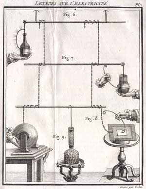
Look at the picture at the right; the worlds first illustration of the working of a Leyden Jar, by Abbe Jean-Antoine Nollet!

Trembley's letter is fascinating as it is one of the earliest first-hand accounts of this new discovery. He happened to be in Holland about the time of the discovery and his letter was the first word to England of the marvelous new jar.

Georg von Kleist tried using an electrostatic generator to place a charge on an iron nail inside a small glass bottle. Again later in 1745, a lawyer by the name of Anreas Cunaeus who frequently visited one the laboratories at the University of Leiden, was trying to electrify water. He used a chain hanging into a flask of water, and brought the end of the chain into contact with an electrostatic generator. In both cases, after disconnecting the generator, the experimenter touched the metal nail or chain inside the flask with one hand while the other hand still surrounded the outside of the container, and got zapped with an electric shock as a result.

But van Musschenbroek and von Kleist were certainly not the only ones playing with static discharge or electromagnetism.
The Greeks, by means of Greek philosopher Thales of Miletus, had already determined that fact in around 600 BC by charging up Lodestone with a piece of amber and a sheeps skin. Lodestone (sometimes called incorrectly Loadstone) was used in ancient times for navigation at sea. Another Greek philosopher, Theophrastus, stated that this power is possessed by other substances about three centuries later.
The first scientific study of electrical and magnetic phenomena, however, did not appear until AD 1600, when the researches of the English physician William Gilbert were published. Gilbert was the first to apply the term electric (Greek elektron, "amber") to the force that such substances exert after rubbing. He also distinguished between magnetic and electric action.

Early Leyden Jars

     Capacitors (also called condensers) are funny things, creating enormous problems when troubleshooting for a fault and yet are absolutely necessary for almost every electronic circuit. They come in a variety of sizes, shapes, models, or if you so desire they can be manufactured by your specifications. They also come in a variety of materials, to name a few: Aluminum foil, Polypropylene, Polyester (Mylar), Polystyrene, Polycarbonate, Kraft Paper, Mica, Teflon, Epoxy, Oil-filled, Electrolyte, Tantalum, and the list goes on. Latest product (in research) is Niobium. The value of a capacitor can vary from a fraction of a pico-Farad to more than a million uFarad (µ means 'micro'). Voltage levels can range from a couple to a substantial couple hundred thousand volts. The largest capacitor in my own collection is 150.000 uF at 10Volts. A big sucker measuring about 10 x 5 inches! Does it still work? You bet! It will still zap the soles of your shoes... I use it on occasion to recondition shorted NiCad batteries which I use for my Radio Control gear.
The basic unit of capacitance is the Farad. Clumsy and not very practical to work with, capacitance is usually measured in microFarads, abbreviated uF, or picoFarads (pF). The unit Farad is used in converting formulas and other calculations. A uF (microFarad) is on millionth of a Farad (10-6 F) and a pF picoFarad is one-millionth of a microFarad (10-12 F).

Plates     What exactly is a 'Capacitor'? A capacitor is a device that stores an electrical charge or energy on it's plates. These plates (see Fig. 1), a positive and a negative plate, are placed very close together with an insulator in between to prevent the plates from touching each other. A capacitor can carry a voltage equal to the battery or input voltage. Usually a capacitor has more than two plates depending on the capacitance or dielectric type.

The 'Charge' is called the amount of stored electricity on the plates, or actually the electric field between theses plates, and is proportional to the applied voltage and capacitor's 'capacitance'.
The Formula to calculate the amount of capacitance is Q = C * V where:
  • Q = Charge in Coulombs
  • C = Capacitance in Farads
  • V = Voltage in Volts

    There is also something else involved when there is 'charge', something stored called 'Energy'.
    The formula to calculate the amount of energy is: W = V2 * C / 2 where:
  • W = Energy in Joules
  • V = Voltage in Volts
  • C = Capacitance in Farads

    elco Is it difficult or complicated to 'charge' a capacitor? Not at all. Put proper voltage on the legs of the capacitor and wait till current stops flowing. It goes very fast. Do NOT exceed the capacitor's working breakdown voltage or, in case of an electrolytic capacitor, it will explode. The break down voltage is the voltage that when exceeded will cause the dielectric (insulator) inside the capacitor to break down and conduct. If that happens the results can be catastrophic. And in case of a polarized capacitor, watch the orientation of the positive and negative poles. A healthy, good quality capacitor (disconnected) can hold a charge for a long time. From seconds to several hours and some for several days depending on its size. A capacitor, in combination with other components, can be used as a filter that blocks DC or AC, being it current, frequency, etc.

    An interesting experiment for a classroom. Try to build another capacitor than the Leyden Jar yourself too. Cut two long strips of aluminum, say 1" wide by 48" long (25mm x 120mm). Cut two strips of paper 1.5" by 50" (38mm x 125mm). Make sure the paper is dry. The paper is a bit wider and longer then the foil to prevent the strips of foil from touching each other when you roll them up and creating a short. Take two small metal paperclips and 'unbend' them. One paperclip/strip aluminum foil is designated 'Positive' and other one 'Negative'. Carefully roll up (all at once) the strips. One paperclip (or wire) goes with it. First layer is tin foil, second one is paper (the insulator), third layer is tin foil, and last layer is paper again. When you're almost at the end, don't forget the insert the other paperclip (or wire) with it. Make sure the paper is dry or it won't work. Don't forget the paperclips (or wire) and make sure the two strips don't touch each other. When you have the whole thing rolled up tightly as possible secure it with tape or an elastic band or whatever.
    Measure with a multimeter that the foil strips are insulated from each other and not shorted.
    Take a 9-volt battery and attach the negative (-) to one pole of the capacitor, and the other to your positive (+) pole. It only takes a fraction of a second to charge it up. You can check the charge by hooking up a voltmeter or if that is not available short the 'capacitor' and you should see a little spark.

    Capacitor Codes
         I guess you really like to know how to read all those different codes. Not to worry, it is not as difficult as it appears to be. Except for the electrolytic and large types of capacitors, which usually have the value printed on them like 470uF 25V or something, most of the smaller caps have two or three numbers printed on them, some with one or two letters added to that value. Check out the little table below.

    Capacitor Codes
    Have a look at Fig. 2 and Fig. 3. As you can see it all looks very simple. If a capacitor is marked like this 105, it just means 10+5zeros = 10 + 00000 = 1.000.000pF = 1000 nF = 1 uF. And that's exactly the way you write it too. Value is in pF (PicoFarads). The letters added to the value is the tolerance and in some cases a second letter is the temperature coefficient mostly only used in military applications, so basically industrial stuff.

    So, for example, it you have a ceramic capacitor with 474J printed on it it means: 47+4zeros = 470000 = 470.000pF, J=5% tolerance. (470.000pF = 470nF = 0.47uF) Pretty simple, huh? The only major thing to get used to is to recognize if the code is uF nF, or pF.

    Other capacitors may just have 0.1 or 0.01 printed on them. If so, this means a value in uF. Thus 0.1 means just 0.1 uF. If you want this value in nanoFarads just move the comma three places to the right which makes it 100nF. Easy huh?

    "NPO" is standard for temperature stability and 'low-noise', it does *not* mean non-polarized even though you might think so because the abbreviation looks similar. Polarized ceramic capacitors do not exist. The abreviation "NPO" stands for "Negative-Positive-Zero" (what is read as an 'O' is actually zero), and means that the negative and positive temperature coefficients of the device are zero--that is the capacitance does not vary with temperature. ONLY the black top indicates NPO qualification and the values are in the range from 1.8pF to 120pF, unless manufactured with different values for Military and/or industrial purposes on special request. They feature 2% tolerance which comes down to about 0.25pF variation, and all are 100V types. You may sometimes find NPO-type caps marked witht he EIA (Electronic Industrial Association) code "COG". The EIA has an established set of specifications for capacitor temperature characteristics (EIC 384/class 1B). Thus, a capacitor labeled "Y5P" would exhibit a plus/minus tolerance of 10% variation in capacitance over a temperature range of -30°C. to +85°C. Or it may say N12 which translates to 120pF. Or 2P2 (2.2pF). I'm sure you get the idea...

    But the average hobbyist uses only a couple types like the common electrolytic and general purpose ceramic capacitors and depending on the application, a more temperature stable type like metal-film or polypropylene.

    Philips Marking SchemeEIA Class II Capacitor Codes

    Dielectric Constant of some materials

    The larger the plate area and the smaller the area between the plates, the larger the capacitance. Which also depends on the type of insulating material between the plates which is the smallest with air. (You see this type of capacitor sometimes in high-voltage circuits and are called 'spark-caps'.) Replacing the air space with an insulator will increase the capacitance many times over. The capacitance ratio using an insulator material is called Dielectric Constant while the insulator material itself is called just Dielectric. Using the table in Fig. 4, if a Polystyrene dielectric is used instead of air, the capacitance will be increased 2.60 times.

    Look below for a more detailed explanation for the most commonly used caps.

    miniElectrolytic - Made of electrolyte, basically conductive salt in solvent. Aluminum electrodes are used by using a thin oxidation membrane. Most common type, polarized capacitor. Applications: Ripple filters, timing circuits. Cheap, readily available, good for storage of charge (energy). Not very accurate, marginal electrical properties, leakage, drifting, not suitable for use in hf circuits, available in very small or very large values in uF. They WILL explode if the rated working voltage is exceeded or polarity is reversed, so be careful. When you use this type capacitor in one of your projects, the rule-of-thumb is to choose one which is twice the supply voltage. Example, if your supply power is 12 volt you would choose a 24volt (25V) type. This type has come a long way and characteristics have constantly improved over the years. It is and always will be an all-time favorite; unless something better comes along to replace it. But I don't think so for this decade; polarized capacitors are heavily used in almost every kind of equipment and consumer electronics.

    tantalumTantalum - Made of Tantalum Pentoxide. They are electrolytic capacitors but used with a material called tantalum for the electrodes. Superior to electrolytic capacitors, excellent temperature and frequency characteristics. When tantalum powder is baked in order to solidify it, a crack forms inside. An electric charge can be stored on this crack. Like electrolytics, tantalums are polarized so watch the '+' and '-' indicators. Mostly used in analog signal systems because of the lack of current-spike-noise. Small size fits anywhere, reliable, most common values readily available. Expensive, easily damaged by spikes, large values exists but may be hard to obtain. Largest in my own collection is 220uF/35V, beige color.


    super caps
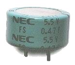
Super Capacitors - The Electric Double Layer capacitor is a real miracle piece of work. Capacitance is 0.47 Farad (470,000 uF). Despite the large capacitance value, its physical dimensions are relatively small. It has a diameter of 21 mm (almost an inch) and a height of 11 mm (1/2 inch). Like other electrolytics the super capacitor is also polarized so exercise caution in regards to the break-down voltage. Care must be taken when using this capacitor. It has such large capacitance that, without precautions, it would destroy part of a powersupply such as the bridge rectifier, volt regulators, or whatever because of the huge inrush current at charge. For a brief moment, this capacitor acts like a short circuit when the capacitor is charged. Protection circuitry is a must for this type.


    polyesther
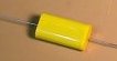
Polyester Film - This capacitor uses a thin polyester film as a dielectric. Not as high a tolerance as polypropylene, but cheap, temperature stable, readily available, widely used. Tolerance is approx 5% to 10%. Can be quite large depending on capacity or rated voltage and so may not be suitable for all applications.

    polypropylene
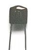
Polypropylene - Mainly used when a higher tolerance is needed then polyester caps can offer. This polypropylene film is the dielectric.
    Very little change in capacitance when these capacitors are used in applications within frequency range 100KHz. Tolerance is about 1%.
    Very small values are available.


    polystyrenePolystyrene - Is used as a dielectric. Constructed like a coil inside so not suitable for high frequency applications. Well used in filter circuits or timing applications using a couple hundred KHz or less. Electrodes may be reddish of color because of copper leaf used or silver when aluminum foil is used for electrodes.


    MetalizedMetalized Polyester Film - Dielectric made of Polyester or DuPont trade name "Mylar". Good quality, low drift, temperature stable. Because the electrodes are thin they can be made very very small. Good all-round capacitor.


    epoxyEpoxy - Manufactured using an epoxy dipped polymers as a protective coating. Widely available, stable, cheap. Can be quite large depending on capacity or rated voltage and so may not be suitable for all applications.


    ceramicCeramic - Constructed with materials such as titanium acid barium for dielectric. Internally these capacitors are not constructed as a coil, so they are well suited for use in high frequency applications. Typically used to by-pass high frequency signals to ground. They are shaped like a disk, available in very small capacitance values and very small sizes. Together with the electrolytics the most widely available and used capacitor around. Comes in very small size and value, very cheap, reliable. Subject to drifting depending on ambient temperature. NPO types are the temperature stable types. They are identified by a black stripe on top.

    multilayer ceramic
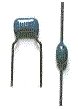
Multilayer Ceramic - Dielectric is made up of many layers. Small in size, very good temperature stability, excellent frequency stable characteristics. Used in applications to filter or bypass the high frequency to ground. They don't have a polarity. *Multilayer caps suffer from high-Q internal (parallel) resonances - generally in the VHF range. The CK05 style 0.1uF/50V caps for example resonate around 30MHz. The effect of this resonance is effectively no apparent capacitance near the resonant frequency.
    As with all ceramic capacitors, be careful bending the legs or spreading them apart to close to the disc body or they may get damaged.


    silver-micaSilver-Mica - Mica is used as a dielectric. Used in resonance circuits, frequency filters, and military RF applications.
    Highly stable, good temperature coefficient, excellent for endurance because of their frequency characteristics, no large values, high voltage types available, can be expensive but worth the extra dimes.


    adjustable capacitors
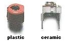
Adjustable Capacitors - Also called trimmer capacitors or variable capacitors. It uses ceramic or plastic as a dielectric.
    Most of them are color coded to easily recognize their tunable size. The ceramic type has the value printed on them. Colors are: yellow (5pF), blue (7pF), white (10pF), green (30pF), brown (60pf). There are a couple more colors like red, beige, and purple which are not listed here. Anyways, you get the idea...

    Tuners
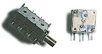
Tuning or 'air-core' capacitors.
    They use the surrounding air as a dielectric. I have seen these variable capacitor types of incredible dimensions, especially the older ones. Amazing it all worked. Mostly used in radio and radar equipment. This type usually have more (air) capacitors combined (ganged) and so when the adjustment axel is turned, the capacitance of all of them changes simultaneously. The one on the right has a polyester film as a dielectric constant and combines two independent capacitors plus included is a trimmer cap, one for each side.


    motor capacitors


    Combining Capacitors & Formula's:

    Is it possible to combine capacitors to get to a certain value like we do with resistors? Certainly! Check below how go about it.

    Capacitors in Parallel

    caps in parallelCapacitors connected in parallel, which is the most desirable, have their capacitance added together, which is just the opposite of parallel resistors. It is an excellent way of increasing the total storage capacity of an electric charge:
    Ctotal = C1 + C2 + C3

    Keep in mind that only the total capacitance changes, not the supplied voltage. Every single capacitor will see the same voltage, no matter what. Be careful not to exceed the specified voltage on the capacitors when combining them all with different voltage ratings, or they may explode. Example: say you have three capacitors with voltages of 16V, 25V, and 50V. The voltage must not exceed the lowest voltage, in this case the 16V one. As a matter of fact, and a rule-of-thumb, always choose a capacitor which is twice the supplied input voltage. Example: If the input voltage is 12V you would select a 24V type (in real life 25V).

    Capacitors in Series

    ceramic
    Again, just the opposite way of calculating resistors. Multiple capacitors connected in series with each other will have the total capacitance lower than the lowest single value capacitor in that circuit. Not the preferred method but acceptable.


    For a regular two capacitor series combo use this simple formula:

    If you have two identical capacitors in series the formula is simplicity itself:


    microFarads (�F)   nanoFarads (nF)   picoFarads (pF)
    0.000001�F = 0.001nF = 1pF
    0.00001�F = 0.01nF = 10pF
    0.0001�F = 0.1nF = 100pF
    0.001�F = 1nF = 1000pF
    0.01�F = 10nF = 10,000pF
    0.1�F = 100nF = 100,000pF
    1�F = 1000nF = 1,000,000pF
    10�F = 10,000nF = 10,000,000pF
    100�F = 100,000nF = 100,000,000pF

    Table 1. Capacitance Conversion

    Capacitor symbols used in schematics Capacitors in Schematics:
          Capacitors in schematics are represented as a pair of plates. Sometimes the plates are drawn as straight lines (a), sometimes as curved ones (d), and sometimes as a combination of the two. Past electronic magazines such as Radio Electronics, Hands-on Electronics, and Popular Electronics used the symbols in fig. (a), (d), (c), and (g). While european magazines such as the Dutch Elektuur (Elektor) uses symbols as depicted in (a), (e), and (f).
    Symbol in (c) is a variable capacitor like a trimmer cap, and (g) is a ganged variable capacitor such as a air-plate capacitor as used in radios.
    Electrolytic capacitors are frequently indicated by a symbol with one straight and one curved line (d) or the european way of drawing this symbol in (e). A '+' sign is placed at the straight line to indicate the anode. Occasionally an electrolytic is drawn as two straight lines, but the plus sign is always included to indicate its polarity.
    When a capacitor is shown as one straight line and one curved one, the curved line, which represents the outer case or electrode of the device, is assumed to be at a lesser potential than the straight one. Thus, since signal flow in a schematic diagram is usually from left to right, capacitors are drawn with their curved ends facing left or, if that is not possible, facing down, which is the direction usually used to represent ground. Electrolytics, especially, are depicted with the curved place facing downward.
    Variable capacitors are usually depicted as shown in © and (f). The arrow is the conventional symbol used to indicate that a device may be adjusted over a range of values. A multi-section variable device may be shown with one symbol for each section, with dashed lines (g) to show that both of the sections are ganged together.
    In schematics, capacitor values are usually indicated in microFarads unles a note specifies that things are otherwise. Voltage ratings, if they are given, are usually indicated in microFarads (uF) unless a note specifies that things are otherwise. Voltage ratings, if they are given, are usually presented as part of a "fraction." A label of "4.7uF/35V" or "4.7/35" would indicate a capacitor with a value of 4.7uF with a a working voltage of 35 volts.
    MicroFarads are indicated with the greek letter 'u' (µ). Don't make the mistake of writing uF as mF. 'm' Stands for 'milli' and is definately not the same.

    Things Capacitors Don't Like:
         Capacitors are very finicky devices. There are any number of conditions they don't like. Many types, for instance, lose a significant amount of their capacitance at high frequencies, making them unsuitable for RF applications. You also have to watch out for the inductance some may introduce in places where you don't want it. For that reason, some types of capacitors are indicated specifically as "non-inductive."
    Temperature extremes are another thing to which capacitors, particularly electrolytics, are sensitive. Electrolytic capacitors, at elevated and at depressed temperatures, lose much of their capacitance. If you are going to operate electrolytics at extremes of temperature, make sure their tolerances extend to that temperature range.
    Most capacitors do not care for Alternating Current (AC) either. It makes them overheat and--before they self-destruct--operate inefficiently. AC in particular is hard on capacitors because of the sinusoidal switching effect. For that reason it is of utmost importance to select a capacitor type with the correct dielectric, temperature coefficient, capacitance, and working voltage. As a rule-of-thumb in DC applications, select a capacitor of at least twice the supply power.

    Polarized capacitors, as they already been pointed out, cannot tolerate reverse voltages. Not only does that make them heat up, it can cause them--especially tantalum types--to heat up so rapidly that a sudden and violent explosion can result (most polarized capacitors are encased in tightly sealed containers).
    Explosions can also result from polarized capacitors being installed "backwards" in a circuit. The cathode (negative) side of a polarized capacitor should always connect to ground.

    Uncommon Capacitors:
         Capacitors vary in size from microscopic to the enormous. At the small end of the scale, there are the capacitors that are deposited on a substrate during the manufacture of integrated circuits. Hybrid integrated circuits such as those containing tuned circuits may require very precise capacitor values--with tolerances that are impossible to achieve using any economically feasible straight manufacturing process.
    The precise capacitances required are obtained by intentionally making the capacitors oversize, and then trimming them with a laser until the circuit of which they are apart resonates at exactly the right frequency.
    At the other end of the scale, the enormous energy requirements of the acceleration devices used in subatomic-particle research are also met by capacitors--rooms full of them! One of the largest such devices, a particle accelerator located outside of Chicago, is said to be able to store enough energy to meet the electrical demand of the entire world! Of course, that's only for an instant during the discharge cycle, but the figure involved is still big enough to boggle the mind.

    Bypassing:
    The phrase "bypass" or "decoupling" is referred to filtering noise off the power rails caused by switching of TTL IC's, MosFets, Transistors, etc. Especially TTL (Transistor-Transistor-Logic) IC's create a lot of noise and so this has to be cleaned up. Mounting a 100nF (0.1uF) ceramic bypass capacitor over the power rails and as close to the IC as possible and keeping the capacitor leads as short as you can, will clean up noise nicely. This has to be done on all IC's and power rails on a printed circuit board with this kind of digital logic. Noise can cause all sorts of problems such as false triggering, cross-talk, change to an undesirable logic state, etc. Decoupling is used where the supply voltage cannot be lowered, i.e., if one needed a noise free +12V on a PC bus, for example. You could get a "clean" +12 volts with a voltage regulator... if only there was +15 volts or higher to start with. But such is not the case. So you use a high "Q" inductor or RFC choke along with the proper bypass capacitor to effectively lowpass filter the +12 volt supply rail. For a real noisy supply you can use more than one inductor: a "pie" network for example.
    As digital becomes faster and faster, it looks more like analog than digital. It would be an asset to have a good understanding of the analog/rf properties of high speed digital. Careful layout of a groundplane and proper decoupling and bypass requires close attention of a circuit design to maintain the integrity of the power distribution.
    Excessive lead length will void the purpose of a bypass capacitor so keep the leads short.

    Couple of Bypass Suggestions:
    If needed, attempt the following as stated below.

  • Use 0.1uF (=100nanoF) or greater, ceramic capacitor, surface mount technology or SMT prefered.
  • One capacitor per SSI, MSI TTL, device.
  • The capacitors should be connected over the Vcc and Gnd with the shortest path possible.
  • Ceramic disc capacitors have the best high frequency characteristics and the least self inductance.
  • Only in RF applications it is appropriate to mix different type caps together to filter at different freq's.
  • Substituting a tantalum for a ceramic type will not work, but they can work together very well.

    The Capacitor Future:
         The future for capacitors looks good. A constant search is going on by companies like Murata, Kemet, etc. Kemet in particular is researching a new type of a dielectric substance called Niobium. Niobium Pentoxide (Nb2O5) offers a higher dielectric constant of 41 in comparison to Tantalum Pentoxide (Ta2O5) at 26. It implies that approximately 1.5 more CV (Capacitance x Voltage rating) can be obtained from the same amount of material, everything else being equal. What does this mean in plain english? Much smaller capacitors with larger capacity, especially important in surface mount technology. Recently, a new type capacitor with very high capacitance has been developed with capacitance designated in Farads! Yes, you read it well, Farads. This type of Electric Double Layer capacitor is known as a "Super Capacitor". I am sure we haven't heard the last of it about this type. At this particular time (2007) capacitors of 5 Farad are already available!


    CAPACITOR NOMENCLATURE -- by Dean Huster

    The questions of reading capacitor values, tolerances and their units of measure come up often on various Internet forums and have hit the old "Q & A" column that I wrote for Poptronics magazine (formerly Electronics Now and Popular Electronics magazines) during its last two years of existence. Here's an attempt at a global treatise on the subject.


    The Farad, MicroFarad and PicoFarad
    Capacitors have always had farad as the unit of measure, abbreviated "F". Since this is a very large unit of measure for most practical capacitors or for most uses of capacitance, you'll find that a millionth of a farad or a million-millionth of a farad are the more common units found on capacitors. Yes, these days we can find capacitors with ratings in the tens and hundreds of farads, but those are usually reserved for extremely high-current, low-voltage switching supplies or for a more frivolous use as energy-storage tanks for use with high-power automotive audio power amplifiers. This treatise is for "normal" capacitors.

    In scientific notation, we would write 1 millionth of a farad as 1 x 10⁻⁶ farad. In electronics, since we deal with so many component values and circuit values on even the smallest schematic or product, the metric prefix form is used for an electronic shorthand to keep the scribbling to a minimum. That prefix form uses letter symbols to take the place of the scientific notation--or more accurately, the engineering notation--that would otherwise accompany a unit of measure. The metric prefix form replaces the engineering notation [Note 1] that would otherwise be used in front of the unit of measure. That list follows.
            Metric Prefix       Symbol    Power of 10 (multiplier)
    
             giga [Note 2]        G            x 10^9
                   mega           M            x 10^6
                   kilo           K            x 10^3
                  (none)                       x 10^0 (same as 1 or unity)
                   milli          m            x 10^-3
                   micro          f            x 10^-6
                   nano           n            x 10^-9
                   pico           p            x 10^-12
    			
    This list does extend farther in either direction, but those larger and smaller multipliers are not as commonly used in electronics. But using this list, you'll find that the common capacitor multipliers in the United States will be f (micro) and p (pico). A capacitor with a value of 3.3fF is the same as a capacitor with a value of 3.3 x 10^-6 farads or 0.0000033 farads. "f", by the way, is the lower-case Greek letter "mu", properly written as our Roman lower case "u" with a leading descender much as a "y" has a trailing descender.


    Antique Capacitors and Schematic Diagrams
    Prior to the 1960s, capacitors were called "condensers". Same part, same function, different name. You'll still hear the old name used by auto mechanics when they speak of the condenser in the ignition system on an older vehicle.

    That earlier list of prefixes, although valid in the hayday of the vacuum tube, was used even less extensively back then. Mega (M) was the largest prefix commonly used and micro (f) was the smallest. To achieve larger or smaller multipliers, the prefixes were doubled up just like multiplying two numbers together. So, a small capacitor value might be 47ffF ("forty-seven micromicro farads") which was saying 47 x 10^-6 x 10^-6, which is the same as 47 x 10^-12, or 47pF. So, anytime you see "ff", just think "p" in your head. [Note 3] You'll also hear some old timers use the rather ridiculous term mickey-mikes instead of saying micromicrofarads. Makes me glad that we went to using pico.

    To make it even worse, the symbol for micro, m, was not used often before 1970 except for expensive physics and engineering texts. It was not a common character to find in a print shop and impossible to find on a typewriter, unless you had the special "symbol" typeball for the IBM Selectric. So, the lower case "u" was usually used in its place. That means that on schematics of the 1950s, a capacitor that was listed as 68uF is the same as one today listed as 68fF. In addition, the components themselves rarely had even the "u" listed. The actual part could have any one of the following printed on it:
     68 mF     68 MF     68 mfd     68 MFD
    It was always understood that "mF", "MF", "mfd" or "MFD" ALWAYS meant microfarad. Microfarad or micromicrofarad were the only units used for capacitors back then, so no one would ever even consider that "mfd" might mean "millifarad" or that "MFD" might mean "megafarad"! Even today, you'll still see "MFD" on capacitors, especially on motor start or motor run capacitors.

    In addition, antique capacitors did not hold to today's standard value system. More on that later.


    The Europeans
    Even while we had nanoseconds and millihenries and other such measurements in the United States, capacitor values were only given in microfarads and picofarads (micromicrofarads) and that holds true even today. I have yet to ever find anyone or any source that can give the reason for that. I'm afraid that "because we've always done it that way" will be the only reason you'll ever hear. The practice thwarts the rules of engineering notation [Note 1], resulting in capacitor values written as 0.0068fF or 6800pF, both of which are the same value and either of which is correctly written in the engineering or metric prefix systems of notation. In addition, in this world of large computer-grade caps, you'll also find values of 180,000fF. Some companies preferred to use the latter of the two forms of notation just to keep the decimal point out of print so that there would be no confusion, preferring for instance, 6800pF over 0.0068fF

    Meanwhile in Europe, and later Asia, the electronics folks there would have no problem at all referring to that same value of 0.0068 fF or 6800pF as 6.8nF (6.8 nanofarads). So, on diagrams from the U.K., don't be surprised to see both millifarads and nanofarads used extensively. And that's OK. It makes a lot more sense and it's easier to write. The only problem is that we Yanks have to learn to convert or at least get used to working with milli and nano when dealing with capacitors. The 180,000fF cap mentioned earlier would be more-correctly rendered as 180mF by someone in Germany.

    Cryptic Capacitor Markings
    In the 1960s, capacitors were marked with their value. Plain and simple. But nevertheless, it was a poor system as decimal points and zeros often got lost. Paper capacitors often had a wax coating on the outside that obscured the markings and these same markings could be accidentally "edited" when scraping the wax away for a better view.
    Similarly, ceramic disc caps also often had a wax coating, possibly just from being next to waxy paper cap in a warm television set. A cap might be marked as ".0047MFD" or simply as ".22" and without that leading zero, there could be problems if the decimal point disappeared. You had to use a little common sense when reading these values. If the value was in decimal form (e.g., ".047"), you assumed the value to be in microfarads. If it was a whole number (e.g., "470"), you had to determine what type of capacitor you had. If it was an electrolytic type, you assumed the value to be in microfarads. If it was a small ceramic cap, it was in picofarads. You knew that a small ceramic or plastic cap couldn't possibly be as large as 470fF and that an electrolytic would nearly always have a value larger than 1fF.

    During the 1970s, manufacturers began to mark the caps in a way similar to the way resistors were done, but without the color code. Rather than colors, they just used the actual printed digits, and the value was marked on the cap as two significant digits and a multiplier, the value being in picofarads. So, a cap marked "221" doesn't mean 221fF or 221pF. It means 22 + 1 zero or 220pF. "684" is decoded as 680,000 (68 + 4 zeros) pF or 0.68fF. Capacitor values smaller than 100pF might be printed as just two digits, such as "33" for 33pF or as two digits with a zero multiplier, as in 330 for 33pF.

    This method of marking caps takes care of a lot of problems with disappearing decimal points and large numbers (e.g., .0047MFD) that would otherwise be difficult to print on small parts. But it did put in a bit of confusion when compared to the older way of marking. What did "100" mean? If it was an older cap, it meant 100pF. If it used the newer marking system, it meant 10pf (10 with no zeros added). So, you need to know which system is in use and that can be tricky.
    That's why it's nice to have a digital capacitance meter or a capacitance bridge at hand. You can get a "ballpark" check of the value to determine where to go from there.

    Later, manufacturers took a hint from the Europeans and begin to mark their capacitors like the Brits marked them on schematics. This took care of ALL the problems of marking as well as problems associated with schematic value markings. In the Euro system, you revert to the engineering form, but replace the decimal point with the metric prefix multiplier. So, the oldest "4.7MFD" capacitor that was updated to "4.7fF" and then to "475" (picofarad) with the later system was now marked as "4f7". Presto! The "f" shows the location of the decimal point AND gives the metric prefix, all at the same time! This is really the best system in the world, both for marking the components themselves and for marking the values on schematics. If a decimal point disappears because of wear or poor printing, it can mess things up in the old system. An entire character would have to disappear in the newest system.

    You will find plenty of folks, especially here in the U.S. who don't like the Euro way of marking. But these same folks don't like change. As a matter of fact, a lot of these old clowns will still use a "33 em-em-eff condenser to set the frequency of their 4.5 megacycle" oscillator. Just ignore them!


    Tolerances
    Value tolerances used to be marked on the capacitor in percentage. An older cap might be marked as ".05 10%", meaning 0.05fF, 10%. Newer caps use a letter for the tolerance, and that will seem confusing right at first. A common value might be ".1M" which means 0.1fF, 20%. A little newer cap might be marked as "332K" and that drives some folks nuts. After all, "K" is a standard metric prefix multiplier and they automatically think they have a 332,000fF cap on their hands. In reality, they have a 3300pF (33 + 2 zeros, in pF) with a ±10% tolerance. The letters on these caps correspond to the following list. I've marked the tolerances that you'll find to be the most common with an asterisk.
                        
                        B = ±0.1pF
                        C = ±0.25pF
                        D = ±0.5pF
                        E = ±0.25%
                        F = ±1.0%
                        G = ±2%
                        H = ±2.5%
                        J = ±5% *
                        K = ±10% *
                        L = ±15%
                        M = ±20% *
                        N = ±30%
                        P = -0, +100%
                        S = -20, +50%
                        W = -0, +200%
                        X = -20, +40%
                        Z = -20, +80% *
    			
    You'll find that the "Z" tolerance of -20, +80% to be common for aluminum electrolytic caps and for disc ceramic caps that are used for what is known as "bulk capacitance" in applications such as power supply bypassing or filtering. These kinds of capacitors are used where it's OK for the value to be a lot larger than nominal, but they don't want it to go very far below that value.

    If you do a lot of analog circuit design and building where you attempt to get frequency-dependent circuits to be as accurate as possible, you'll see or want to find Mylar caps with a "G" or "F" tolerances of ±2% or ±1% respectively. They're harder to find in catalogs, but if you watch the electronics surplus catalogs, you can find then on a sporadic basis. The tolerances of "B" through "E" are in pF vs. percent and are normally used on small caps of around 10pF or less.


    Standard Values
    When the numbers on a capacitor begin to rub off because of age, and you need to know the value, it may help to know that at least in more modern times, manufacturers have adhered to a set of standard values for capacitors. Typically, these will be the same list of standard values used for 20% tolerance fixed resistors, each decade having six possible values. This simply means that the significant digits of any capacitor value will be either 10, 15, 22, 33, 47 or 68. You'll find that 10, 22, 33 and 47 are the most-commonly used. This set of standard values applies whether the capacitor has a tolerance of 20%, 10% or 5%.

    Why not have the full 24-per-decade range of values for the 5% capacitors just like we do for resistors? In most cases where tolerance might be a factor, a capacitor is used against a resistor for setting some type of timing or frequency of a circuit. There's no sense having all of those values for both components. So, since the capacitor is a lot more expensive to manufacture and is prone to larger tolerance variations, they limit the number of values to six per decade. A designer will then choose the value of capacitor most closely suited to the application and then "fine tune" the actual RC time constant by choosing one of the 24-per-decade resistor values. If the circuit is to be very accurate and stable, the designer will choose a 2% or 1% tolerance capacitor with a low temperature coefficient and then use a 1% metal film resistor for the resistive element where there are 96 possible values per decade.

    All this is to say that if you're trying to decide if that capacitor you're trying to replace in a radio is marked "65" or "68" because the last digit is all scratched up, choose "68" since that's a standard value and is most likely the marked value. This is not to say that a capacitor will always hold to the standard value table. Older capacitors had values such as 0.03fF or 0.05fF. These were made before extensive standardization. And then there are specially made caps for the telephone industry. I've seen values such as 0.1746fF with a 2% tolerance. All those significant figures with a 2% tolerance is foolish since even the "4" can move up or down by almost three digits and still be within tolerance. And some manufacturers will feel the need to "fill in" the table by providing values that conform to the 12-per-decade table of 10% components, but that's OK.

    Just don't expect it for all capacitors.


    Voltage Ratings
    In addition to value and tolerance, a capacitor is often marked with a voltage rating. These may simply be noted as "50V" or "50VDC" or some such other voltage as appropriate. Voltage ratings are sometimes incorporated into a capacitors "coded description". For instance, the value code "2A104K" has a "2A" prefix which translates to a voltage rating of 100V. The "104K" part, as you now know, translates to 100,000pF or 0.1fF or 100nF with a tolerance of 10%. Voltage prefixes include:
                                         1E       25V
                                         1H       50V
                                         2A       100V
    Since this seems to be European in nature, these voltage markings are new territory for me. I would appreciate more information on this so that I can flesh out this article and make it more accurate. My e-mail address appears in the "Wrapup" section following in case you would like to contact me with some of this information. I try to be accurate, so please make sure that you include source material rather than depending upon hand-me-down folklore!


    Temperature Coefficient
    Capacitors, most notably ceramic capacitors, have temperature coefficients ("tempco" or TC). That is, their value will change with a change in temperature. Some "bulk" ceramic capacitors (those "M" tolerance things) can change over 10 or 20 percent with a 20 degree shift in temperature, so are unsuitable for use in circuits that are frequency-dependent, such as oscillators or filters. Capacitance changes are not necessarily linear or even directly proportional at all times for a particular type of capacitor.

    You'll see markings on a cap such as "Z5U". That's a temperature coefficient. The "Z" part has nothing to do with the tolerance. I have no intention of going into tempcos here since it has nothing to do with reading the value. I just wanted you to be aware of them so that you don't confuse them with the tolerance.


    Wrapup
    As usual, if you find any errors, however small, in this article or if you feel there's some information that needs to be added, please don't hesitate to contact me at: dhhuster at semo dot net (don't forget to use "@" for "at" and "." for "dot"). If everyone wants to see tempco information here, then I'll go ahead and add it.


    Footnotes
    Note 1: While scientific notation takes the form, n.nnnnn x 10^p where you have only one digit to the left of the decimal point and an appropriate power of 10 so that the number in scientific notation will be numerically equal to the original number in decimal form, engineering notation takes one of the three following forms, n.nnnnn x 10^3p, nn.nnnn x 10^3p, nnn.nnn x 10^3p, where there are either one, two or three digits to the left of the decimal point to achieve a power of ten that is an integer multiple of three, the final number being numerically equal to the original number in decimal form or scientific notation form. So, the only powers of 10 allowed in engineering notation are powers such as 15, 12, 9, 6, 3, 0, -3, -6, -9, -12, -15, etc. Engineering notation is handy in that it directly translates into the metric prefix form, which also uses powers of ten that are integer multiples of three. Some models of Casio scientific calculators are capable of displaying their results in engineering notation while some even have the capability of displaying in metric prefix form.

    The metric prefix form follows the engineering form exactly with two common exceptions. The "bel", the unit of measure for a ratio of sound or signal amplitude levels, it too large to be practical.
    One-tenth of a bel, or a decibel, is the normal unit used, abbreviated "dB", a term you have probably seen often. "Deci" is the same as "x 10^-1".
    Another exception is the centimeter, often used in the metric system where we would use inches in the English or SAE system. A centimeter is 1/100 of a meter, abbreviated "cm". "Centi" is the same as "x 10^-2".

    Note 2: "giga" is technically pronounced "jigga" beginning with a soft "g" as in the word "giant" with a hard "g" as in "gallup" the second time, and as is done by the character of Dr. Emmett Brown in the motion picture "Back to the Future" when he refers to "one point twenty-one gigawatts of power." However, you'll find that nearly everyone involved in electronics pronounces it beginning with a hard "g" as they would the "g" in the word "go".

    Note 3: Other units of measure had similar doubling up. For instance, fast oscilloscope risetimes were noted as 3mfs or "3 millimicro seconds" which is the same as today's 3ns. At the other end of the spectrum, so to speak, microwave signal generators were marked as having frequencies of 1.5KMC or "1.5 kilomega cycles (per second)" which is 1.5GHz in today's vernacular. In addition, "cycles per second" as the unit of measure of frequency, which was usually shortened to the erroneous "cycles", was changed to Hertz, abbreviated Hz, in the 1960s.

    Thanks Dean for your contribution, much appreciated!

    Email note from Bas Viel
    I received an email from Bas Viel, the Netherlands, see below.

    Email in regards to the Engineering button [ENG} on a calculator, not every calculator has one.
    There is a Table 1 for conversion at the capacitors page. No need for it!

    Only remember REN or LEP

    If you have a value what isnot in engineering notation and you want it to be, just move the decimal digit left or right, but... what is the new exponential value?
    REN stands for move digit to the Right, Exponential goes (more) Negative!
    LEP is the opposite for moving the digit to the left.

    No calculator or Table needed!


    Copyright & Credits:
    "Leyden Jars" and portrait of "van Musschenbroek". Reprint with permission from John D. Jenkins. More antique equipment and apparatus can be viewed at John's website called The Spark Museum. This website contains a treasure of information and pictures, from vacuum tubes to radio transmitters. If it is antique, John probably has it. I spend literally several weeks browsing and reading through his website. Amazing piece of work!

    "Capacitor images on this page". Reprint with permission from Terence Noone, President of The Capacitor Industries Companies which consists of Motor Capacitors Inc., Chicago Condenser Corp., and SEI Capacitors Inc.
    For detailed information please visit The Capacitor Industries Companies website.
    "Capacitor Nomenclature", by Dean Huster. Contributing author/editor for our leading electronic magazines. Thanks Dean. It's an honor adding your nomenclature to this tutorial!


    Suggested Reading:
    "The Radio Amateur Handbook" from the American Radio Relay Leaque (ARRL). Good resource.
    "The Capacitor Book". by Cletus J. Kaiser., C.J. Publishing. ISBN: 0-9628525-3-8
    "Williamson Labs". Website about bypassing, decoupling, shielding, layout, etc. (http://williamson-labs.com)

    Return to More Tutorials here.

    Copyright © 2001 - Tony van Roon (VA3AVR), ALL RIGHTS RESERVED
    Last updated: December 18, 2009