© by Tony van Roon
 Coil/Inductance
History:
First a bit of history about this remarkable invention of 'electro-magnetism'.
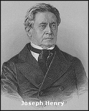
Joseph Henry (1797-1878), was one of the many brilliant US scientists who invented and used the electro-magnetic
'coil' in his university laboratory. His low-power electro-magnet could control a make-and-break switch in a high-power
circuit. Henry believed the potential was in the electro-magnet's use as a control system or device in manufacture, but
he was only really interested in the science of the electricity. The electro-magnet or 'relay' was a laboratory trick
to entertain his students. Samuel Morse later adapted Henry's electro-magnetic-relay device after re-designing it (and
claiming it as his own by patent) using thinner wire, to carry morse-code signals over long kilometers of wire.
In 1846, Joseph Henry was professor of natural philosophy (physics) at the
 College of New Jersey (now known as
Princeton University). He had published scientific articles on a wide variety of subjects, including electro magnetism,
optics, acoustics, astrophysics, molecular forces, and terrestrial magnetism, but his reputation was built primarily
on his work in basic and applied electro magnetism. Among his discoveries in electro magnetism were mutual induction,
self-induction, the electro magnetic relay--enabling him to devise the first electro magnetic telegraph that could be
used over long distances--and the concept of the electric transformer. He also invented the first electric motor.
Henry was often referred to as the scientific successor to Benjamin Franklin. Today, it is the general opinion that
Joseph Henry was the inventor of the telegraph and not Samuel Morse, who did not have a technical background to begin
with. Samuel Morse adapted the ideas and inventions of Henry (and Vail) into his own and patented it, making him the
owner.
It is certain that Joseph Henry was important to the history of the telegraph in two ways. First, he was responsible
for major discoveries in electro magnetism, most significantly the means of constructing electromagnets that were
powerful enough to transform electrical energy into useful mechanical work at a distance. Much of Morse's telegraph
did indeed rest upon Henry's discovery of the principles underlying the operation of such electromagnets.
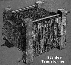
Then in 1885, William Stanley (1858-1916), Jr. built the
first practical alternating current device based on Lucien Gaulard and Josiah Willard Gibbs' idea. This device was
called an induction coil and was very primitive. It was the precursor of the modern transformer. His coil became the
prototype for all future transformers and made practical the transmitting of electricity for consumer uses such as
lighting.
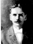 Born in Brooklyn, New York,
William Stanley attended private schools before enrolling at Yale University. He began to
study law at age 21 but less than a semester later left school to look for a job in the emerging field of electricity.
"Have had enough of this," wrote the 21-year-old Yale freshman in 1879. "Am going to New York." With these words,
William Stanley abandoned the career pattern that his father had laid out for him - college, law school, and membership
in the family law firm - and set out instead on the more risky and exciting path of electrical invention.
The decision marked the beginning of a productive career whose highlights included the invention of the modern type of
transformer, and the creation of the business enterprise that was to become General Electric's Pittsfield Works.
Stanley's first job was as an electrician with one of the early manufacturers of telegraph keys and fire alarms. He then
worked in a metal-plating establishment before joining Hiram Maxim, inventor of the machine gun and already a pioneer
in the electrical industry. As Maxim's assistant, Stanley directed one of the country's first electrical installations,
in a store on New York's Fifth Avenue. Stanley gave early evidence of his ability and enthusiasm. As his first employer,
inventor Hiram S. Maxim described him: "Mr. Stanley was very young. He was also very tall and thin, but what he lacked
in bulk, he made up for in activity. He was boiling over with enthusiasm. Nothing went fast enough for him." This
dynamism helped him gain an outstanding reputation in the early electrical industry.
In the 1880s every system for distributing electricity used direct current (DC). But DC transmission over long
distances was impractical. Transmitting at low voltage required thick wires. Transmitting at high voltage was
dangerous and could not be reduced for consumer uses such as lighting. It was known that alternating current (AC)
voltage could be varied by use of induction coils, but no practical coil system had been invented.
 Inventor and industrialist
George Westinghouse learned of Stanley's accomplishments and hired him as his chief engineer
at his Pittsburgh factory. It was during this time that Stanley began work on the transformer. Actually the first
practical AC transformer was developed by Frenchman Lucien Gaulard and Englishman John Gibbs; improvements were made at
the Ganz company in Budapest. Westinghouse instructed Stanley and his assistants, Schmid and Shallenberger, to make
tests to determine the commercial value of the Gaulard and Gibbs system. He also arranged to have a number of the
transformers and a Siemens alternating-current generator forwarded from England to Pittsburgh. Stanley, working under
the direction of Westinghouse, devised a further improvement, which consisted in securing the enclosure of the coils by
making the core of E-shaped plates, the central projections of each successive plate being alternately inserted
through prewound coils from opposite sides, thus permitting separate winding and consequently the better insulation of
the coils. This form was further improved by Albert Schmid, who extended the ends of the arms of the E to meet
the central projection. When inserting these plates the extensions were temporarily bent upward, and upon being released
each plate formed a closed magnetic circuit about the sides of the coils.
In 1885, ill health almost cut short his career--some say he worked himself too hard. But it proved a disguised blessing,
because it necessitated a move to his family home, Great Barrington, Massachusetts. In those peaceful surroundings, he
was able to develop some ideas he had suggested two years earlier to his employer, George Westinghouse (who helped
finance Stanley's lab) for a new type of transformer. This work resulted, on March 20, 1886, in the demonstration of a
prototype system of high voltage transmission employing Stanley's parallel connected transformer. This system was used
by him to provide lighting for offices and stores on the town's Main Street.
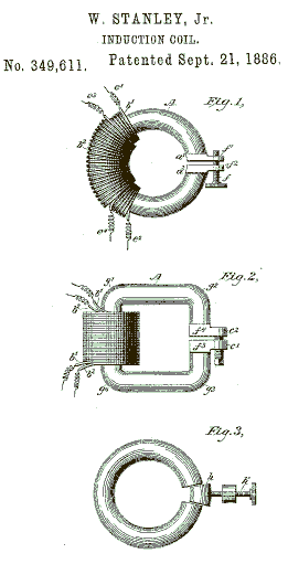
Stanley received a patent on his transformer: "Induction-Coil", Patent No. 349,611. These various inventions and
discoveries led up within a year to commercial production of transformers of high efficiency and excellent regulating
qualities. The development was a fine engineering performance in speed and in quality. The most important single
contribution was by Stanley. He brought out the parallel connection in which the transformers are connected in parallel,
across the constant-potential alternating-current system, instead of being arranged in series, as in the Gaulard and
Gibbs connection. He obtained patents on the method, involving the construction of transformers in which the counter
electromotive force generated in the primary coil of the transformer was practically equal to the electromotive force
of the supply circuit. This is obvious now, but in 1886, when the principles and characteristics of the alternating
current were practically unknown, it was a wonderful invention, and revolutionary in character.
On this invention Stanley's fame largely rests. Of course Stanley did not discover or invent a theory of counter
electromotive force before any one else had thought of it. Such fundamental things seldom happen in invention. His
claim to great and original merit rests on the discovery of a theory which was new to him and the use of it in making a
structure of immense importance in the affairs of men. Briefly, all transformers now made are
built upon practically the same principles as those that were developed in these early products of the Westinghouse
Company.
 Assisted by William Stanley,
George Westinghouse worked to refine the transformer design and build a practical AC power
network. In 1886, Westinghouse and Stanley installed the first multiple-voltage AC power system in Great Barrington,
Massachusetts. The network was driven by a hydro power generator that produced 500 volts AC. The voltage was stepped up
to 3,000 volts for transmission, and then stepped back down to 100 volts to power electric lights.
In 1890 Stanley established the Stanley Electric Manufacturing Company in Pittsfield, Massachusetts, to make transformers
and auxiliary electrical equipment as well as electrical appliances. To organize it, he joined forces with two talented
associates: John J. Kelley, an outstanding designer of motors: and a former Stanley laboratory worker, Cummings C.
Chesney. The company was purchased by General Electric in 1903. Stanley also developed the alternating-current watt-hour
meter, making it possible to measure electricity use with a high level of accuracy. Stanley with E. P. Thomson had also
invented an incandescent lamp with a filament of carbonized silk. During his lifetime he was granted 129 patents
covering a wide range of electric devices. William Stanley died on May 14, 1916.
Inductance:
Inductance (L) is the property of an electrical circuit whereby changes in current flowing in the circuit produces
changes in the magnetic field such that a counter EMF is set up in that circuit or in neighboring ones. If the
counter EMF is set up in the original circuit, it is called self-inductance and if it is set up in neighboring
circuit it is called mutual inductance.
The unit of inductance is the Henry (H) and is defined as that value of inductance in which an induced EMF of
one volt is produced when the inducing current is varied at the rate of one ampere per second. The henry is commonly
sub-divided into several smaller units, the milliHenry (10-3 Henry) abbreviated mH, the
microHenry (10-6 Henry) abbreviated uH, and the nanoHenry (10-12 Henry)
abbreviated nH.
The storage of energy in a magnetic filed is expressed in joules and is equal to LI2/2 and the
dimensions are in watt-seconds.
 Mutual Inductance:
When one coil is near another, a varying current in one will produce a varying magnetic field which cuts the turns of the
other coil, inducing a current in it. This induced current is also varying, and will therefore induce another current
in the first coil. This reaction between two couple circuits is called mutual inductance, and can be calculated
and expressed in henrys.
The symbol for mutual inductance is M. Two circuits thus joined are said to be inductively coupled.
Tee magnitude of the mutual inductance depends on the shape and size of the two circuits, their positions and
distances apart, and the permeability of the medium. The extent to which two inductors coupled is expressed by a
relation known as coefficient of coupling (k). This is the ratio of the mutual inductance actually present at
the maximum possible value.
Thus, when k is 1, the coils have the maximum degree of mutual induction.
The mutual inductance of two coils can be formulated in terms of the individual inductances and the coefficient of
coupling with the formula: 
 Inductors in Series:
Inductors in series are, just like resistors, additive. Provided that no mutual inductance exists.
In this case, the total inductance L is: L = L1 + L2 + ... etc.
Where mutual inductance does exist: L = L1 + L2 + 2M
Where M is the mutual inductance.
This latter expression assumes that the coils are connected in such a way that all flux linkages are in the same direction,
i.e. additive. If this is not the case and the mutual linkages subtract from the self-linkages, the following
formula should be used: L = L1 + L2 - 2M
Where M is the mutual inductance.
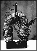
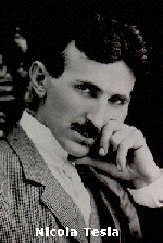
"Why is this picture from Nikola Tesla here" you may ask. Well, like Joseph Henry, Tesla was decades ahead of time.
Tesla had his own variety of "transformer" look-alike while experimenting with his high-voltage inventions.
Core Material:
Ordinary magnetic cores cannot be used for radio frequencies because the "eddy current and hysteresis losses" in the
core material become enormous as the frequency is increased. The principal use for conventional magnetic cores is in
the audio frequency range below approximately 15,000 hertz, whereas at very low frequencies (50 or 60Hz) their use is
mandatory if an appreciable value of inductance is desired.
Copper Wire Table:
Below is part of an example of a so called "Copper Wire Table" with the most popular gauge #'s and associated diameter in
milli-meters. I did not specify the 'Mills' or 'Capacity' specs. A 'Mil' is 1/1000 (one thousandth) of an inch.
But this information can be found in the ARRL Handbook for Radio Amateurs which is available at your local library.
Gauge Ohms per Diameter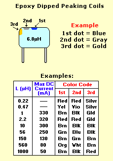 (ga) 1000 feet in mm
18 6.510 1.024
19 8.210 .9116
20 10.35 .8118
21 13.05 .7230
22 16.46 .6438
23 20.76 .5733
24 26.17 .5106
25 33.00 .4547
26 41.62 .4049
27 52.48 .3606
28 66.17 .3211
29 83.44 .2859
30 105.2 .2546
31 132.7 .2268
32 167.3 .2019
33 211.0 .1798
34 266.0 .1601
35 335.0 .1426
36 423.0 .1270
37 533.4 .1131
38 672.6 .1007
39 848.1 .0897
 Inductor (Coil) Color Code:
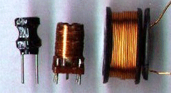
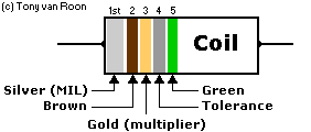
Very seldom a small coil or rf-choke will have the value stamped on them. Even the larger coils don't show anything
but a code. They get a 'color-code' painted on them much like resistors have but usually only 3 bands or 3 dots, unless
they are made by 'Mil Spec' (Military Specification). I opted for a couple of the most commonly used types as an
example. The body itself may have a variety of colors depending on the dipped substance used.
This type of coil can be found everywhere these days and I'll take them from whatever board I can. Old vcr and
television boards have lots of them. Keep a couple around, just in case.
There is more information here about toroids, cores, and chokes: [Toroids and RF]
Suggested Reading:
"Handbook of Electronics Tables and Formulas", by Howard W. Sams & Co., ISBN: 0-672-22469-0
"Radio Handbook", by William I. Orr, W6SAI, Howard W. Sams & Co.,(#22424), ISBN: 0-672-22424-0
"American Radio Relay League", or 'ARRL' book. Any handbook of the ARRL of any year will do.
Copyright and Credits:
This document and tutorial is Copyright © by Tony van Roon (VA3AVR)- 2003, ALL RIGHTS RESERVED
Re-posting or taking graphics in any way or form of this project is expressly prohibited by international
copyright ©laws.
Back to Gadgets Page.
Copyright © 2003 - Tony van Roon, VA3AVR
Last updated: December 18, 2009


 Coil/Inductance
History:
 College of New Jersey (now known as
Princeton University). He had published scientific articles on a wide variety of subjects, including electro magnetism,
optics, acoustics, astrophysics, molecular forces, and terrestrial magnetism, but his reputation was built primarily
on his work in basic and applied electro magnetism. Among his discoveries in electro magnetism were mutual induction,
self-induction, the electro magnetic relay--enabling him to devise the first electro magnetic telegraph that could be
used over long distances--and the concept of the electric transformer. He also invented the first electric motor.
Henry was often referred to as the scientific successor to Benjamin Franklin. Today, it is the general opinion that
Joseph Henry was the inventor of the telegraph and not Samuel Morse, who did not have a technical background to begin
with. Samuel Morse adapted the ideas and inventions of Henry (and Vail) into his own and patented it, making him the
owner.
 Born in Brooklyn, New York,
William Stanley attended private schools before enrolling at Yale University. He began to
study law at age 21 but less than a semester later left school to look for a job in the emerging field of electricity.
"Have had enough of this," wrote the 21-year-old Yale freshman in 1879. "Am going to New York." With these words,
William Stanley abandoned the career pattern that his father had laid out for him - college, law school, and membership
in the family law firm - and set out instead on the more risky and exciting path of electrical invention.
 Inventor and industrialist
George Westinghouse learned of Stanley's accomplishments and hired him as his chief engineer
at his Pittsburgh factory. It was during this time that Stanley began work on the transformer. Actually the first
practical AC transformer was developed by Frenchman Lucien Gaulard and Englishman John Gibbs; improvements were made at
the Ganz company in Budapest. Westinghouse instructed Stanley and his assistants, Schmid and Shallenberger, to make
tests to determine the commercial value of the Gaulard and Gibbs system. He also arranged to have a number of the
transformers and a Siemens alternating-current generator forwarded from England to Pittsburgh. Stanley, working under
the direction of Westinghouse, devised a further improvement, which consisted in securing the enclosure of the coils by
making the core of E-shaped plates, the central projections of each successive plate being alternately inserted
through prewound coils from opposite sides, thus permitting separate winding and consequently the better insulation of
the coils. This form was further improved by Albert Schmid, who extended the ends of the arms of the E to meet
the central projection. When inserting these plates the extensions were temporarily bent upward, and upon being released
each plate formed a closed magnetic circuit about the sides of the coils.
 Assisted by William Stanley,
George Westinghouse worked to refine the transformer design and build a practical AC power
network. In 1886, Westinghouse and Stanley installed the first multiple-voltage AC power system in Great Barrington,
Massachusetts. The network was driven by a hydro power generator that produced 500 volts AC. The voltage was stepped up
to 3,000 volts for transmission, and then stepped back down to 100 volts to power electric lights.
 Mutual Inductance:

 Inductors in Series:
(ga) 1000 feet in mm 18 6.510 1.024 19 8.210 .9116 20 10.35 .8118 21 13.05 .7230 22 16.46 .6438 23 20.76 .5733 24 26.17 .5106 25 33.00 .4547 26 41.62 .4049 27 52.48 .3606 28 66.17 .3211 29 83.44 .2859 30 105.2 .2546 31 132.7 .2268 32 167.3 .2019 33 211.0 .1798 34 266.0 .1601 35 335.0 .1426 36 423.0 .1270 37 533.4 .1131 38 672.6 .1007 39 848.1 .0897
 Inductor (Coil) Color Code: