NE555 Timer/Oscillator
Data sheet
Similar to: LM555-SE555C-MC1455P1-NTE955M-ECG955M
by Tony van Roon
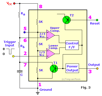
The NE555 silicon monolithic timing circuit is a highly stable controller capable of producing accurate time delays, or oscillation. In the time delay mode of operation, the time is precisely controlled by one external resistor and capacitor. For a stable operation as an oscillator, the free running frequency and the duty cycle are both accurately controlled with two external resistors and one capacitor. The circuit may be triggered and reset on falling waveforms, and the output structure can source or sink up to 200 mA.
Features:  Turn off time less than 2 micro seconds.
Maximum operating frequency greater than 500KHz.
Timing from microseconds to hours.
Operates in both astable and monostable modes.
High output current.
Adjustable duty-cycle.
TTL compatible.
Temperature stability of 0.005% per °C.
Rise and Fall times of output is 100nS typical.
The MC1455 (cmos) has a normally "on" or normally "off".
The MC1455 (cmos) output can also drive MTTL circuits.
The MC1455 (cmos) is direct pin-compatible with the NE555 timers.
Some Applications:
Precision Timing.
Pulse generation.
Sequential timing.
Time delay generation.
Pulse width modulation.
Pulse position modulation.
Missing Pulse Detector (used in Crashed Aircraft Locator article).
Absolute Maximum Ratings:
Supply voltage for SE555 +18 volt. For NE555 & SE555C +16 volt.
Discharge current (pin 7) is 200mA.
Power dissipation 600 milliWatts. For the MC1455 is that 680mW.
Operating temperature range for NE555 0 to 70 °C, for SE555 & SE555C -55 to -125 °C.
Storage temperature range from -65 to -150 °C.
Lead temperature (soldering, up to 60 sec) 300 °C.
Suffix's: The 'G' suffix (e.i. xx555G) stands for Metal package (can), case 601-04.
The 'P1' suffix stands for Plastic package (the most common), case 626-05.
The 'U' suffix stands for Ceramic package (mostly used in the Industry), case 693-02.
The 'L' suffix stands for Ceramic package (mostly used in the Industry), case 632-08.
The 'D' suffix stands for Surface Mount, Plastic package, case 751-02 or SO-8.
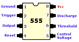
The 'D, N, or FE' suffix can be found for the 8-pin dip packages.
The 'F' suffix is the 14 pin version of the 8-pin dip. Pins 2,5,7,9,11, and 13 are not connected.
Notes:
Supply current when output high typically 1mA or less.
Tested at Vcc=5V and Vcc=15V.
This will determine the maximum value of Ra+Rb, for 15V operation, the max total
R = 10 megohm, and for 5V operation, the max total of R = 3.4 megohm.
Specified with trigger input high.
Time measured from a positive going input pulse from 0 to 0.8 x Vcc into the threshold
to the drop from high to low of the output. Trigger is tied to threshold.

Back to Gadgets Menu page
Copyright © Tony van Roon


