Noise Trap for long Servo leads
by Tony van Roon
Introduction
What exactly is a 'Noise-Trap' you ask? A noise-trap takes care of noise or interference picked up by long servo leads.
It filters a noisy signal into a sharp filter. Two examples are the rudder servo of a helicopter and the aileron servo
of an airplane. Noise Traps (or filters) are normally located between the receiver and close to the servo.
Operation
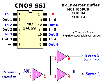
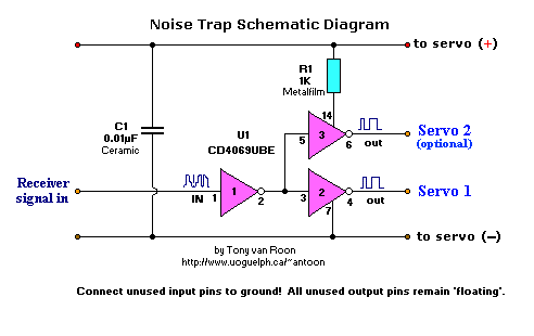
The input signal (pulse) from the receiver is introduced at pin 1 of the CMOS chip MC14069UB and comes out at pin 2
inverted, gets put back on pin 3 of the second buffer, and gets out on pin 4 inverted again. Any noise or interference
picked up by long servo leads will be cleaned up by the two inverter buffers. The 10nF (0.01uF) ceramic filter capacitor
takes care of the tiny bits of noise produced by RF, inferior or noisy servo motors, or heavily used older servos no
longer properly blocking feedback. If you're planning to use a 'Y' lead for your ailerons, then solder an other
jumper from pin 5 to pin 3 of the MC14069U. The second output (pin 6) goes to the other servo, plus add another 10nF
cap. The low input current is approximately 1uA (microAmp) for the MC14069U, I have not measured the current
draw for the regular 4069U.
Also note that the IC *must* be a 4069U or 14069U type.
This type is an unbuffered model and used because of the 1K resistor in series with Vcc. (Too many fets for one gate
will probably result in malfunction.)
| Inputs A |
Outputs Y |
| L |
H |
| H |
L |
Construction:
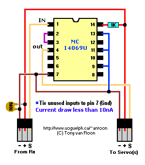
The noise-trap is very easy to construct and can be done on vero-board or any other point-to-point wiring you prefer.
The only two major components are the 14069U CMOS IC and the 10nF (nanoFarad) filter capacitor. If you don't have a
10nF type just use whatever you have from about 470pF (picoFarad) and up. It is not all that critical. Just don't go
overboard!
Make sure to tie all unused inputs to an appropriate logic level (ground or +). Unused
outputs MUST be left open! There are six of these hex
inverters in this chip and only three are used. The other three are spares or use them for something else. Before
wrapping the Noise Trap with heat shrink tubing test it first to make there are no wiring errors.
 Final Notes:
A direct substitute is the 74HC04 or 74C04 which is pin-compatible with the 14069U IC. Although both are of the CMOS
type, the major difference is the supply voltage. The high-impedance MC14069UB can handle an operating voltage range
of +3v to +18v and the 74HC04 +2v to +6v. I like the double diode protection of the MC14069UB. On the other hand,
the 74HC04 has higher noise immunity characteristics. The chip complexity of the 74HC04 is: 36 FET's or 9 equivalent
gates. Do NOT try to use the regular 7404 or 74LS04. They are not the same and behave different then the 74HC04.
This 14069U (or 4069U) chip contains protection circuitry to guard against damage due to high static voltages or
electric fields. However, make sure not to exceed the maximum rated voltage levels.
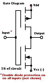
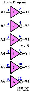
The MC14069UB hex inverter is constructed with MOS P-channel and N-channel enhancement mode devices in a single
monolithic structure. These inverters are excellent where low power and/or high noise immunity is desired. There are
six inverters available and each of these six inverters is a single stage to minimize propagation delays.
I have not experimented with Schmitt Trigger devices (MC14106B, 14584B, 74HC14, etc) which were specifically designed
to eliminate noise, but are much more expensive.
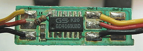
The enlarged picture above shows the surface mount SOIC version, and outputs for two servos. True size is 1/4" x 3/4".
A parts-KIT (no pcb) is available: [R/C Noise Eliminator]
Back to Gadgets Menu page
Copyright ©1996 Tony van Roon


 Final Notes: