A Time-Delayed Model-Rocket Launch Control
by Tony van Roon
"Add a touch of class and safety with this deluxe model-rocket launch control
circuit."
Since the introduction of low-cost model rocket engines in the 1950's, building and launching small scale model rockets
have been popular pastimes. While designing and finishing high-performance models is both interesting and challenging,
it is also fun to design and build electronic gadgets to go along with them. One such gadgets is the Time Delayed
Launch Control in this article.
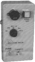
With the Time Delayed Launch Control, you press the fire switch to initiate a launch sequence, then the circuit begins
to count-down, giving you plenty of time to step back so that you can view the impending event from a safe distance,
record the launch, or prepare to monitor experiments during the flight. At the end of a preset period, the circuit
ignites the rocket's engine, sending it skyward.
The circuit has six preset delay intervals: 5, 10, and 30 seconds, and 1, 5, and 10 minutes. The circuit also contains
a piezo-electric buzzer that beeps every few seconds as the system counts down to launch. As a safety feature, a
launch sequence can be aborted at any time, simply by shutting off the system or by switching to the test-mode.
The main function of the test mode, however, is to verify, via a front panel indicator, that the ignition circuit is
properly wired. The circuit is powered from its own internal battery pack, which also provides power to the rocket-
engine igniter.
Circuit Description:
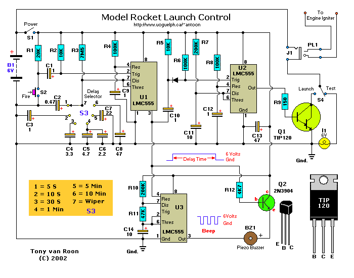
A schematic diagram of the Time Delayed Launch Control is shown in Fig. 1. The circuit--which gives a choice of 6 delay
settings--is comprised of three 555 timer/oscillators (U1, U2, U3), a pair of transistors (Q1 and Q2), four switches
(S1 - S4), a piezo electric buzzer (BZ1), and a few support components. Power for both the control circuit and the
rocket-engine igniter is provided by a 6-volt power source that is comprised of 4 AA-cell alkaline batteries. Alkaline
batteries are specified because other types are incapable of supplying the 1-3 amps required to fire a rocket-engine
igniter. Closing switch S1 feeds power to the launch control circuit, but does not initiate a launch sequence.
A pair of series RC circuits (R4/C9 and R8/C12, respectively) are used to debounce the reset inputs (pins 4) of U1 and
U2 (a pair of 555 oscillator/timer IC's), thereby, preventing false triggering from occurring during power-up or when
switching modes. Pull-up resistors R1 and R2 effectively shunt capacitor C1, keeping it discharged until S2 (Fire) is
momentarily closed. When S2 is closed, C1's negative terminal is connected to ground through the switch, momentarily
pulling pin 2 of U1 (which is configured as a monostable multivibrator, or one-shot) low, activating it.
Once triggered, U1's output goes high for an interval that's determined by R3 and one os six timing capacitors
(C2 through C8). The timing capacitor is selected via Delay Selector switch S3. Positions 1 through 6 of
S3 give intervals of 5, 10, or 30 seconds or 1, 5, or 30 minutes, respectively.
The high output of U1 at pin 3 is fed through current-limiting resistor R12 to the base of Q2, forward biasing it, which
causes Q2 to turn on, allowing the piezo-buzzer (BZ1) to turn on when the proper signal is applied to BZ1's negative
terminal. Monostable U1's output is also fed to the reset input of U3 (which is configured as an astable multivibrator
or oscillator) at pin 4, causing it to oscillate with a duty cycle of about 75% (as determined by C14, R10, and R11).
As long as the output of U1 is high and the astable is oscillating, BZ1 beeps once every 4 seconds.
Resistor R5 discharges coupling capacitor C10 whenever U1's output goes high, while R6 maintains the normally high bias
voltage required at U2's trigger input (pin 2). At the end of the selected time delay, U1's output goes low. That low
is coupled through C10 and D1 to the trigger input (pin 2) of U2, which (like U1) is configured as a monostable
multivibrator.
Components R7 and C11 set U2's high-output interval to approximately 3 seconds. During that 3-second interval, U2's
high output at pin 3 is fed to Darlington transistor Q1 through R9 (which limits the bias current to the device to
less than 40 mA). With S4 in the Launch position, Q1 grounds one end of the engine igniter, effectively
connecting it to the battery's negative terminal. During that 3-second interval, approximately 1-3 amps passes
through the engine igniter, causing it to glow and burn.
For a detailed description, workings, and pins of the 555 timer/oscillator, please
click here.
Construction:
To assemble the launch-control circuit, you will need all of the components listed in the parts list. You will probably
want to customize the project, so pick out switches, a lamp, and a piezo-buzzer that will give our launch control an
interesting and personalized appearance.
Start with the enclosure. The enclosure must be large enough to accommodate the printed circuit board and all of
the front panel controls, and still leave room for the quad AA-cell battery pack. The overall dimensions of the
enclosure should be about 6 x 3 inches. It is recommended that the circuit be housed in a brightly-colored ABS plastic
enclosure. A plastic enclosure is recommended because you will have to drill about ten holes in it, and ABS plastic is
much easier to work with than steel or aluminum.
Choose a convenient location on the front panel for the test lamp (I1), the piezoelectric buzzer (BZ1), and the four
switches (S1-S4). Mark and drill the mounting holes for those components. Then drill a hole in the side of the enclosure
for the phono jack J1. It should be located about 2 inches from the end of the enclosure where the battery pack will
go. Clean any burrs from the holes and check all front-panel components for a proper fit, but do not mount them yet.
If you are unable to find a brightly colored enclosure, you can spray-paint the one you choose after all the mounting
holes have been drilled and deburred. If you must paint the enclosure, apply 2 or 3 thin coats of primer (or white),
followed by 2 thin coats of a bright-colored paint. Give each coat a couple hours to dry before applying the next
coat, then let it set overnight. Just a word of caution; make sure the primer you are using is compatible with your
final paint.
With that done, use dry-transfer (rub-on) lettering to label each switch position according to its function--the rotary
switch with its delay times should be marked at each stop--and test the lamp.
After labeling, protect the dry transfer lettering by applying one of two coats of clear lacquer. Allow all coats to
dry several hours or overnight. The front panel is now ready for assembly. Mount BZ1, I1, and S1-S4, and J1 to the
enclosure, and don't forget to install a knob on the shaft of S3.
Since the control circuit contains only three IC's and two transistors, you can easily assemble it on a small piece of
perfboard or 'Vero-board' using wire-wrap or point-to-point wiring techniques. However, the author's prototype was
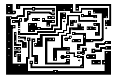
assembled on a printed circuit board that measures about 2 by 2-13/16 inches. A full-size template of that pcb lay-out
is shown in Fig. 2. Once you have etched the board, drill all holes with a No. 67 bit. That bit size will
accommodate all of the component leads and the 22 & 26 AWG hookup wire that will be used for the interconnections
between the board and the panel mounted components.
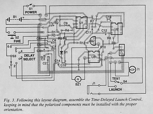
Following the parts placement diagram shown in Fig. 3, install the capacitors, making sure that they are all flush to
the board, while observing their polarity. Likewise, install the resistors flat against the board. That minimizes
lead lengths and give a neater appearance. Install an 8-pin DIP socket at all IC (U1-U3) locations. That helps
eliminate the possibility of damaging the IC's which are static sensitive during soldering. Next, install transistors
Q1 and Q2, taking care to properly align the emitter, base, and collector leads. Then, using hookup wire, or the excess
leads clipped from the resistors, install the 5 jumper connections in the locations shown.
Cut six 8-inch lengths of 26 AWG stranded hookup wire. Twist pairs of wires together, making three pairs in all. Next,
cut five 8-inch lengths of 22AWG stranded hookup wire. Twist three of these wires together to make a 3-lead set for S4,
and then twist the remaining pair together for S1. Once that is done, strip about an 1/8th inch of insulation from the
ends of all the leads.
Solder one 26 AWG pair to the two printed circuit pads that are identified as BZ1 in Fig. 3. Being careful to observe
the correct polarity, solder the other ends of those leads to BZ1. Similarly, install the other two 26 AWG leads
between the printed circuit board and lamp I1, and the printed circuit board and S2. Next, install the 3-conductor
22 AWG wire set between the printed circuit board and S4. Be careful to identify each of the three printed circuit
pads corresponding to the appropriate terminals of S4. Then solder the remaining 22 AWG pair between the printed
circuit board and S1.
Rotary switch S3 requires a 7-conductor cable. Use either 26 AWG or 28 AWG ribbon cable for S3. Cut an 8-inch length
of 7-conductor cable and strip 1/8th inch from all ends. Following that, solder the cable to the appropriate printed
circuit board pads. Next, solder the other end of the cable to the rotary switch, making sure that lead number seven
connects to the wiper. Install and solder the two leads coming from the battery holder to the printed circuit board.
Again, be certain to identify the correct polarity of each lead and each printed circuit pad.
For the engine-igniter leads, cut two 3-foot or more lengths of 22 AWG stranded hookup wire. The actual length of this
wire set depends on how far you want to place the control box from the launch pad--mine are about 3 feet. Once you have
decided on the length, twist them together and strip about an 1/8th inch insulation from both ends of each conductor.
Solder a micro clip to one end of each lead. Push the other ends of the leads through the phone-plug sleeve, solder the
two free ends to the tip and ring terminals of the phono plug, and then install the sleeve.
Finally, fasten the printed circuit board to the enclosure using a 1-inch length of double-sided foam tape between the
bottom of the printed circuit board and the inside of the enclosure. That is easier than using mounting hardware, and
gives a neater overall appearance. Works just as good.
Test and Use:
Set S3 to the 30 S position, S4 to the Test position, and install 4 AA Alkaline batteries in the quad
battery holder. Attach an engine igniter to the two micro clips and insert phone-plug PL1 into jack J1; the test lamp,
I1, should light. Now switch S4 to the Launch position, turn on S1 and press S2, Fire. The piezo buzzer
(BZ1) should begin to beep every few seconds. After about 30 seconds, the beeping stops, and the igniter fires.
Warning: Always pull the phone plug from its jack before attaching the micro clips to a
live engine! Also do not allow the micro clips to short during a launch or test;
otherwise transistor Q1 could be damaged. I would suggest to cover the clips with electrical tape or something.
Should any of the above tests fail, troubleshoot the circuit using a DC voltmeter. To do so, attach the meter's
negative probe to ground, turn S1 on, and measure the voltage at pin 8 of each 555 timer--you should get a reading of
approximately 6 volts. If so, check the voltage at pin 3 of U1, and then press S2. The voltage should remain near
6 volts during the time-delay interval and then go to zero. Similarly, at pin 3 of U2, the voltage should be at 6
volts for approximately one out of every 4 seconds. At pin 3 of U3, it should change from zero to 6 volts at the
end of the time delay, and then return to zero. If any of those tests fail, recheck all solder connections and
component values associated with the defective timer.
If you don't want to spend the extra moneys on pcb switches and other stuff, do as you wish. It is not mandatory. You
may have already some switches you like to use. There is just a little bit of extra wiring required. No problem, use
whatever you like. Just in case you were thinking of using NiCad batteries for the AA battery pack; NiCads will not
work, although they are called 'AA' in reality they do not provide 1.5 V but rather 1.25 volt. Times 4 that gives
only 5 volt instead of the required 6 volt.
The Time-Delayed Launch Control makes a great weekend project. Since all of the parts are inexpensive and come in
a variety of shapes and sizes, the control panel can take on a customized look, limited only by your imagination. So
heads up and happy flying!

Parts List and other components:
Semiconductors:
U1-U3 = LMC555CM, MC1555, NTE955MC, or similar CMOS timer.
   Q1 = TIP120, SK3180, NTE261,(or similar) NPN darlington transistor.
   Q2 = 2N3904, NTE123AP, or similar general purpose NPN silicon transistor.
   D1 = 1N4148, NTE519, or similar general purpose silicon signal diode.

Resistors:
All Resistors are 5%, 1/4-watt
      R1 = 20K
   R2,R5 = 10K
      R3 = 7M5 (7.5M)
R4,R6,R8 = 100K
  R7,R10 = 200K
      R9 = 150 ohm
     R11 = 47K
     R12 = 4K7 (4.7K)

Capacitors:
All Capacitors are Radial Lead Electrolytic
C1,C3,C9,C10,C12 = 1uF, 16V
              C2 = 0.47uF, 16V
              C4 = 3.3uF, 16V
              C5 = 4.7uF, 16V
              C6 = 2.2uF, 16V
              C7 = 22uF, 16V
          C8,C13 = 47uF, 16V
         C11,C14 = 10uF, 16V

Additional Parts & Materials:
 B1 = See text
 S1 = SPST toggle switch
 S2 = Momentary (Normally Open) pushbutton switch
 S3 = SP6T rotary switch
 S4 = SPDT toggle switch
 J1 = Phone jack
PL1 = Phone plug
BZ1 = Piezo-electric buzzer
 I1 = 6V Incandescent lamp
PCB materials, enclosure, 7-conductor ribbon cable, quad AA-cell battery holder
and connector, micro-alligator clips, knob, 22 AWG and 26 AWG stranded hook-up
wire, solder, hardware, etc.
For Radio Shack part numbers click on this RS data sheet.


Click Here for the PCB Diagram
I fully support this project. Most parts can be obtained via your local Radio Shack or Tandy
store. I will answer all questions but via the message forum only. Tony's Message Forum can be accessed
via the main page, gadgets, or circuits page.
Copyright and Credits:
The original project was written by Dan Becker. Reproduced from Popular Electronics, May 1994, by permission of
Gernsback Publishing, Inc. Document updates & modifications, all diagrams, PCB/Layout redrawn by Tony van Roon.
Re-posting or taking graphics in any way or form of this project is expressily prohibited by international
copyright © laws.
Back to R/C Gadgets page
Copyright © 2002 - Tony van Roon
Last updated: October 25, 2008


