"LED's can really dress up a project as well as provide a user with the necessary information, so learning to use
them properly is important to the look and use of your circuits. Technology and availability of high intensity LED resources can make your
circuits look amazing."
© 2010 by Joseph J. Carr and Tony van Roon
 Light Emitting Diode History:
Captain Henry Joseph Round (2 June 1881, Kingswinford, Staffordshire, England�17 August 1966, Bognor Regis) was one of the early pioneers of radio
and received 117 patents. He was a personal assistant to Guglielmo Marconi.
However, no practical use was made of the discovery for several decades.[18] Independently, Oleg Vladimirovich Losev published "Luminous carborundum
[[silicon carbide]] detector and detection with crystals" in the Russian journal Telegrafiya i Telefoniya bez Provodov (Wireless Telegraphy and
Telephony).[19] Losev's work languished for decades.
The first practical LED was invented by Nick Holonyak, Jr., in 1962 while he was at General Electric Company. The first LEDs became commercially
available in late 1960s, and were red. They were commonly used as replacements for incandescent indicators, and in seven-segment displays, first in
expensive equipment such as laboratory and electronics test equipment, then later in such appliances as TVs, radios, telephones, calculators, and
even watches. These red LEDs were bright enough only for use as indicators, as the light output was not enough to illuminate an area. Later, other
colors became widely available and also appeared in appliances and equipment. As the LED materials technology became more advanced, the light output
was increased, and LEDs became bright enough to be used for illumination.
Most LEDs were made in the very common 5 mm T1-3/4 and 3 mm T1 packages, but with higher power, it has become increasingly necessary to get rid of
the heat, so the packages have become more complex and adapted for heat dissipation. Packages for state-of-the-art high power LEDs bear little
resemblance to early LEDs (see, for example, Philips Lumileds).
A light emitting diode (LED) is essentially a PN junction semiconductor diode that emits a monochromatic (single color) light when operated in a
forward biased direction. The basic structure of an LED consists of the die or light emitting semiconductor material, a lead frame where the die is
actually placed, and the encapsulation epoxy which surrounds and protects the die.
 The phenomenon of electroluminescence was first observed in a piece of Silicon Carbide (SiC), in 1907 by Henry Joseph Round. The yellow light emitted
by it was too dim to be of practical use and difficulties in working with Silicon Carbide meant that research was abandoned. Further experiments were
carried out in Germany in the late 1920s by Bernhard Gudden and Robert Wichard Pohl, using phosphor materials made from Zinc Sulphide doped with
Copper (ZnS:Cu), although once again, the low level of light produced meant that no in depth research was carried out. In 1936 George Destriau
published a report on the emission of light by Zinc Sulphide (ZnS) powders, following the application of an electric current and is widely credited
with having invented the term "electroluminescence".
The phenomenon of electroluminescence was first observed in a piece of Silicon Carbide (SiC), in 1907 by Henry Joseph Round. The yellow light emitted
by it was too dim to be of practical use and difficulties in working with Silicon Carbide meant that research was abandoned. Further experiments were
carried out in Germany in the late 1920s by Bernhard Gudden and Robert Wichard Pohl, using phosphor materials made from Zinc Sulphide doped with
Copper (ZnS:Cu), although once again, the low level of light produced meant that no in depth research was carried out. In 1936 George Destriau
published a report on the emission of light by Zinc Sulphide (ZnS) powders, following the application of an electric current and is widely credited
with having invented the term "electroluminescence".
The first commercially usable LEDs were developed in the 1960's by combining three primary elements: gallium, arsenic and phosphorus (GaAsP)
to obtain a 655nm red light source. Although the luminous intensity was very low with brightness levels of approximately 1-10mcd @ 20mA, they still
found use in a variety of applications, primarily as indicators. Following GaAsP, GaP, or gallium phosphide, red LEDs were developed. These devices
were found to exhibit very high quantum efficiencies, however, they played only a minor role in the growth of new applications for LEDs. This was due
to two reasons: First, the 700nm wavelength emission is in a spectral region where the sensitivity level of the human eye is very low (Figure 2)
and therefore, it does not "appear" to be very bright even though the efficiency is high (the human eye is most responsive to yellow-green light).
Second, this high efficiency is only achieved at low currents. As the current increases, the efficiency decreases. This proves to be a disadvantage to
users such as outdoor message sign manufacturers who typically multiplex their LEDs at high currents to achieve brightness levels similar to that of
DC continuous operation. As a result, GaP red LEDs are currently used in only a limited number of applications.
As LED technology progressed through the 1970's, additional colors and wavelengths became available. The most common materials were GaP green and red,
GaAsP orange or high efficiency red and GaAsP yellow, all of which are still used today (Table3). The trend towards more practical applications was
also beginning to develop. LEDs were found in such products as calculators, digital watches and test equipment. Although the reliability of LEDs has
always been superior to that of incandescent, neon etc., the failure rate of early devices was much higher than current technology now achieves. This
was due in part to the actual component assembly that was primarily manual in nature. Individual operators performed such tasks as dispensing epoxy,
placing the die into position, and mixing epoxy all by hand. This resulted in defects such as "epoxy slop" which caused VF (forward voltage) and VR
(reverse voltage) leakage or even shorting of the PN junction. In addition, the growth methods and materials used were not as refined as they are
today. High numbers of defects in the crystal, substrate and epitaxial layers resulted in reduced efficiency and shorter device lifetimes.
It wasn't until the 1980's when a new material, GaAlAs (gallium aluminum arsenide) was developed, that a rapid growth in the use of LEDs began to
occur. GaAlAs technology provided superior performance over previously available LEDs. The brightness was over 10 times greater than standard LEDs
due to increased efficiency and multi-layer, heterojunction type structures. The voltage required for operation was lower resulting in a total power
savings. The LEDs could also be easily pulsed or multiplexed. This allowed their use in variable message and outdoor signs. LEDs were also designed
into such applications as bar code scanners, fiber optic data transmission systems, and medical equipment. Although this was a major breakthrough in
LED technology, there were still significant drawbacks to GaAlAs material. First, it was only available in a red 660nm wavelength. Second, the light
output degradation of GaAlAs is greater than that of standard technology. It has long been a misconception with LEDs that light output will decrease
by 50% after 100,000 hours of operation. In fact, some GaAlAs LEDs may decrease by 50% after only 50,000 -70,000 hours of operation. This is especially
true in high temperature and/or high humidity environments. Also during this time, yellow, green and orange saw only a minor improvement in brightness
and efficiency which was primarily due to improvements in crystal growth and optics design. The basic structure of the material remained relatively
unchanged.
| Wavelength |
Color |
Material and structure of LEDs |
Production method |
| 700 |
Red |
GaP: Zn-O/GaP |
LPE |
| 660 |
Red |
GaAI0.35 As/GaAs |
LPE |
| 630 |
Red |
GaAs0.35PO.65: N/GaP |
VPE + diffusion |
| 610 |
Orange |
GaAs0.25Po.75: N/GaP |
VPE + diffusion |
| 590 |
Yellow |
GaAs0.15PO.85: N/GaP |
VPE + diffusion |
| 565 |
Green |
Gap: N/GaP |
LPE |
| 555 |
Green |
GaP/GaP |
LPE |
|
 To overcome these difficult issues new technology was needed. LED designers turned to laser diode technology for solutions. In parallel with the
rapid developments in LED technology, laser diode technology had also been making progress. In the late 1980’s laser diodes with output in the
visible spectrum began to be commercially produced for applications such as bar code readers, measurement and alignment systems and next generation
storage systems. LED designers looked to using similar techniques to produce high brightness and high reliability LEDs. This led to the development
of InGaAlP (Indium Gallium Aluminum Phosphide) visible LEDs. The use of InGaAlP as the luminescent material allowed flexibility in the design of LED
output color simply by adjusting the size of the energy band gap. Thus, green, yellow, orange and red LEDs all could be produced using the same basic
technology. Additionally, light output degradation of InGaAlP material is significantly improved even at elevated temperature and humidity.
To overcome these difficult issues new technology was needed. LED designers turned to laser diode technology for solutions. In parallel with the
rapid developments in LED technology, laser diode technology had also been making progress. In the late 1980’s laser diodes with output in the
visible spectrum began to be commercially produced for applications such as bar code readers, measurement and alignment systems and next generation
storage systems. LED designers looked to using similar techniques to produce high brightness and high reliability LEDs. This led to the development
of InGaAlP (Indium Gallium Aluminum Phosphide) visible LEDs. The use of InGaAlP as the luminescent material allowed flexibility in the design of LED
output color simply by adjusting the size of the energy band gap. Thus, green, yellow, orange and red LEDs all could be produced using the same basic
technology. Additionally, light output degradation of InGaAlP material is significantly improved even at elevated temperature and humidity.
British experiments into electroluminescence, using the semiconductor Gallium Arsenide (GaAs) in the 1950s led to the first "modern" Light Emitting
Diode (LED), which appeared in the early 1960s. It is said that early experimental laboratory LEDs needed to sit in liquid nitrogen while operating
and considerable effort was required to make the breakthroughs needed to create devices that would function efficiently at room temperature. The first
commercial LEDs were only able to produce invisible, infra red light, but still quickly found their way into sensing and photo-electric applications.
The first visible (red) light LEDs were produced in the late 1960s, using Gallium Arsenide Phosphide (GaAsP) on a GaAs substrate. Changing to a
Gallium Phosphide (GaP) substrate led to an increase in efficiency, making for brighter red LEDs and allowing the color orange to be produced.
By the mid 1970's Gallium Phosphide (GaP) was itself being used as the light emitter and was soon producing a pale green light. LEDs using dual GaP
chips (one in red and one in green) were able to emit yellow light. Yellow LEDs were also made in Russia using Silicon Carbide at around this time,
although they were very inefficient compared to their Western counterparts, which were producing purer green light by the end of the decade.
The use of Gallium Aluminum Arsenide Phosphide (GaAlAsP) LEDs in the early to mid 1980s brought the first generation of superbright LEDs, first in
red, then yellow and finally green. By the early 1990's ultrabright LEDs using Indium Gallium Aluminium Phosphide (InGaAlP) to produce orange-red,
orange, yellow and green light had become available.
The first significant blue LEDs also appeared at the start of the 1990's, once again using Silicon Carbide - a throwback to the earliest semiconductor
light sources, although like their yellow Russian ancestors the light output was very dim by today's standards. Ultrabright blue Gallium Nitride (GaN)
LEDs arrived in the mid 1990s, with Indium Gallium Nitride (InGaN) LEDs producing high-intensity green and blue shortly thereafter.
The ultrabright blue chips became the basis of white LEDs, in which the light emitting chip is coated with fluorescent phosphors. These phosphors
absorb the blue light from the chip and then re-emit it as white light. This same technique has been used to produce virtually any color of visible
light and today there are LEDs on the market which can produce previously "exotic" colors, such as aqua and pink.
Scientifically minded readers may have realized by now that the history of LEDs has been a long, slow "crawl up the spectrum", starting with infra-red.
Indeed, the most recently developed LEDs emit not just pure violet, but genuine ultra-violet "black" light. How much further up the spectrum LEDs can
"go" is a matter of speculation, but who knows? it may one day even be possible to produce LEDs which emit X-rays.
However, the story of LEDs has not just been about color, but brightness too. Like computers, LEDs are following their own kind of "Moore's Law",
becoming roughly twice as powerful (bright) around every eighteen months. Early LEDs were only bright enough to be used as indicators, or in the
displays of early calculators and digital watches. More recently they have been starting to appear in higher brightness applications and will continue
to do so for some time to come. For instance: all American traffic signals will have been replaced with LEDs by late 2005; the automotive industry has
sworn to banish all incandescent bulbs from cars by the end of the decade, replacing them with LEDs - even in headlights. Most of the large video
screens seen at outdoor events use many thousands of LEDs to produce video pictures. Very soon, LEDs will be bright enough to light our homes, offices
and even our streets as well. The extreme energy efficiency of LEDs means that solar charged batteries can power LED units by night, bringing light to
the Third World and other areas with no mains electricity.
The once humble Light Emitting Diode has truly come of age and is now making the jump from mere indicator to true... ILLUMINATOR !
To read some more indept history and indept pre-history, read this article by Steve Bush:
"50 year history of the LED":
by Steve Bush, September 2010
Back in 1960 Electronics Weekly was born into a ferment of III-V semiconductor research that within two years would produce the first practical LED.
In 1960 Dr Nick Holonyak of General Electric was developing an unusual material, GaAsP, as a route to wide bandgap tunnel diodes.
When an infra-red GaAs semiconductor laser was demonstrated in 1962, Holonyak with his wider bandwidth GaAsP was in the perfect position to have a
go at making a visible version.
With advice from GaAs laser pioneer and fellow GE employee Dr Robert Hall, Holonyak made his visible laser later in 1962.
It this October 1962 paper on the GaAsP laser for which Holonyak became known as the father of the LED � where LEDs are defined as visible light
emitters based upon minority carrier injection and radiative recombination of excess carriers.
The same material is still used to produce deep red LEDs today. Holonyak had another connection with early light emitters. He had been John
Bardeen�s first graduate student, the same Bardeen that invented the transistor at Bell Labs in 1947 with Walter Brattain and William Shockley.
Shockley, along with Howard Briggs and James Haynes, applied for a patent on infrared LEDs in both silicon (1.1�m) and germanium (800nm) as early
as 1951.
The silicon device only appears to have worked at liquid nitrogen temperatures, but the germanium LED worked cryogenically and at room temperature.
1951 is an early year for LEDs, but it not the first.
Pre-history:
Marconi�s assistant Henry Round �reported light emission from carborundum (raw silicon carbide) �and other substances� in a 1907 letter to
Electrical World when he was working on cat�s whisker detectors (diodes) for radio. From SiC, he saw a yellowish light at low voltage, then yellow,
light green, orange and blue at higher voltages on different points of different crystals. �In all cases tested, the glow appears to come from the
negative pole, a bright blue-green spark �appearing at the positive pole�, he wrote. Round noted a possible link between the voltage across the
carborundum junction and the light emission.
No other records of semiconductor light emission are known until the mid-1920s when self-educated Russian scientist Oleg Losov also noticed light
emission from SiC, as well as zinc oxide radio detectors. No one knows if Losov had heard of Rounds observation. Light from SiC detectors could
have been common knowledge. What is known is that Losov looked deep into the subject, publishing multiple scientific papers in Russia, England and
Germany between 1924 and 1930 describing the spectrum of light emission in relation to the current-voltage characteristics of SiC cat�s whisker
diodes.
Losov�s discoveries include establishing the v=eV/h formula that links diode voltage drop to emission frequency and, in 1927, he patented a �light
relay�: probably the first reference to LED-based optical comms.
In a possible prelude to Brattain, Bardeen and Shockley�s transistor work, Losov was working on an amplifying three-terminal semiconductor device
during the siege of Leningrad in 1941, in which his paper on the subject was lost when he later died of starvation.
Surprisingly, this is not the first know reference to transistor-like devices as Edgar Liliendfeld filed a Canadian patent in 1925 on a FET-like
device using copper sulphide, including a radio receiver design in which to use it.
Back with cold light emission, the impressively named Zoltan Bay together with Gyorgy Szigeti pre-empted LED lighting in Hungry in 1939 by patented
a lighting device based on SiC, with an option on boron carbide, that emitted white, yellowish white, or greenish white depending on impurities
present. The patent does not mention junctions, and light emission is said to be related to applied voltage, rather than at a fixed voltage that
even Round postulated, so this may have only been non-junction electroluminescence.
Another early character to have touched LEDs is Kurt Lehovec, who is best known for inventing junction isolation for integrated circuits when he
worked for Sprague, patenting it in 1959. Less well known is that in 1952 he applied for a patent on SiC visible light LEDs. He appears to have
grown n-type SiC doped with arsenic, then locally introducing boron with an electron beam to make p-SiC for the junction. In the patent he speaks
of �activator� impurities including silver, lead, manganese, bismuth, thallium, tin, copper, zinc, cerium, europium and samarium which are proposed
to control the colour of light, noting blue, greenish-yellow and pale yellow emission.
Lehovec seems to have made a manganese activated SiC LED, measuring operation to over 200kHz, and proposes it be used to record the audio track
down the edge of movie film. Also worth a mention are Rubin Braunstein and Egon Loebner, working at RCA, who in 1958 patented a green LED made
from a lead antimonide dot alloyed to p-type Ge.
First infrared LEDs:
There followed the blossoming of II-VI, III-V and IV-IV research out of which Holonyak�s first GaAsP red LED sprang.
John von Neumann had theoretically considered the essential elements of a semiconductor laser in 1953, and in 1961 it had been known for some years
that GaAs p-n junctions could emit photons. Research groups in the US, UK, Russia and France were all attempting to turn semiconductor laser theory
into practice.
In mid-1962 Robert Keyes and Theodor Quist at MIT, and a group led by Jacques Pankove at RCA, revealed high efficiency infra-red emissions from
GaAs p-n junctions ��infrared LEDs, and combining this with a GaAs photodiode transmitted TV signals optically from a mountain into the MIT
laboratory. That August, James Biard and Gary Pittman of Texas Instruments filed a patent on GaAs infrared LEDs.
Following on from the MIT work, and still in 1962, Gunther Fenner under Robert Hall at GE used GaAs to make the first semiconductor diode laser.
A visible LED :
This first laser kicked off a month of activity in which Robert Rediker at MIT, Holonyak at a different GE lab, and Marshall Nathan at IBM all made
lasers. All but Holonyak�s were infrared, using Zn diffusion into n-type GaAs, whereas Holonyak�s was his red-emitting GaAsP device � also
credited with being the first alloy compound semiconductor device demonstrated.
Holonyak had been working on GaAsP on GaAs substrates, as well as GaAsP on GaAsP (with a different As/P ratio) substrates since 1960 for his tunnel
diodes � possibly making the first hetero-junction semiconductor devices in the process.
He went on to join the University of Illinois where he became the supervisor of aspiring GaAsP LED �researcher George Craford.
With his PhD from Illinois and inspiration from Holonyak, Craford moved to Monsanto in 1967 and with a team of researchers invented �orange, yellow
and green LEDs using GaAsP on GaAs substrates. The key was nitrogen doping, the idea for which Craford credits a presentation by a Bell Labs
researcher � Bell Labs was working with GaP LEDs, trying both ZnO and N as dopants.
Monsanto was probably the first firm to make affordable LEDs. Crayford moved on to HP in 1969, heading a group that pioneered AlGaAs for bright
red LEDs and AlInGaP for bright orange and green.
LED as bulb replacement:
By 1987 AlGaAs LEDs from HP were bright enough to replace light bulbs in vehicle brake lights and traffic lights, the first time LEDs displaced
incandescent bulbs in a lighting application. AlInGaP followed in 1990, offering at least double the brightness of AlGaAs. HP also made a success
of GaP materials, initially as bright green LEDs in 1993, then the next year as a transparent substrate that got a further 4x improvement in
reddish-orange AlInGaP LEDs for car turn indicators. Craford is now CTO at white LED maker Lumileds which, with Avago, is one of the two
descendants of HP�s LED business.
As the 1980s became the 90s, the spectrum of LEDs was completed when blue LEDs, albeit dim blue LEDs, based in SiC finally went into production
from the likes of Siemens, Sanyo and later Cree.
The story now moves across the Pacific where in 1988 researchers at Nichia, a chemical company little-know outside Japan, start studying GaN as an
LED material. Just like US-based Pankove had in 1971, many could see GaN�s emissive potential if only route to p-GaN could be established so a
p-n junction could be made.
The best minds at the best labs in Japan were on the case when, at Nichia in 1991, researcher Masayuki Senoh succeeded where all others had failed
and produced p-type GaN. His technique was electron irradiation on a magnesium-doped substrate � not suitable for production, but enough to allow
Nichia III-V growth expert Shuji Nakamura make the first p-n junction GaN LED � a homo-structured blue-violet device on a sapphire substrate.
White LEDs:
By the end of September 1991, Nichia researcher Naruhito Iwasa discovered a production compatible way to make p-GaN � annealing Mg-doped GaN above
600�C. With the added development of Zn+Si doping by 1993 the firm was shipping blue GaN LEDs that were 100x brighter than Cree�s SiC types.
Iwasa also found a way to get enough indium into InGaN to pull the wavelength down to blue-green for traffic lights, and by added quantum wells the
firm finally had a pure green InGaN device by the end of 1995.
Like HP before it, Nichia was a hotbed of innovation which finally led it to opened the door to white LEDs, and ultimately lighting class LEDs.
Nichia researcher Yoshinori Shimizu � initially as part of a programme to make blue die emit green - identified YAG phosphors as materials tough
enough to survive in an LED. Yasunobu Noguchi then developed a gadolinium YAG phosphor that could convert blue light to �yellow, and Kensho Sakano
combined Noguchi�s phosphor with a blue LED die to make a white LED.
(Here ends the article by Steve Bush. Nice work Steve!)
 Most people (whether technical or non-technical) like projects that light-up more than ones that just sit there. Apart from just our simple
fascination with light, blinking indicators give us a feeling that "something" is going on.
Most people (whether technical or non-technical) like projects that light-up more than ones that just sit there. Apart from just our simple
fascination with light, blinking indicators give us a feeling that "something" is going on.
On a more serious level, illuminated indicators can provide the user with important information about a circuit's operation, even its lack of
operation. The most popular indicator on hobbyist-built and commercial electronic devices is probably the LED or "Light Emitting "Diode". So it
behooves the hobbyist to know about how to use them wisely and to full advantage, and that is why this article was written; To share some basic design
techniques for LED-driver circuits, and provide a few useful LED applications.
A Variable Brightness Circuit:
Figure 1a shows a graph of LED output for various levels of diode current. The two curves in Fig. 1a
were created from data taken from the test set-ups shown in Figs. 1b/1c. When building those circuits each silicon
solar cell was mounted in a light-tight box that had its interior painted with flat black anti-reflective paint. A common red LED was mounted in each
box such that its light fell directly on a solar cell less that 1 cm away.
A solar cell becomes somewhat more linear when it is heavily loaded. So to linearize the cell and provide an indication of output current, it was
shunted with a milliammeter resulting in the circuit in Fig. 1b. The resulting output current gives us a relative measure
of LED light output.
The scheme shown in Fig. 1C also uses a milliammeter as the output indicator. However, the solar cell is loaded by a
47-ohm resistor, so the meter reads the relative voltage across the resistor. This can also be used as a relative measure of the LED's intensity.
Since the resulting curves are nearly linear for most of their range, the light intensity can obviously be controlled by varying the current flow through
the LED. In other words, we can make a variable-brightness control by controlling the current through the LED. Figure 2 shows
the use of a variable resistor, R2, for that purpose. The LED current (I) in amps is equal to:
I = ((V+) - Vled) / ( R1 + R2)
The voltage drop across an LED is typically around 1.8 volts, so you can use that value for Vled in your calculations.
The value of fixed resistor R1 should be selected so that current I does not exceed its maximum allowable value when V + is at its maximum value or when
the resistance of R2 is zero. For example, assume that the maximum value of V + is 11.8 volts DC, and Imax is 20mA.
The value of R1 is found by setting R2 to zero and solving the previous equation for R1:
R1 = ((V +) - Vled ) / Imax
R1 = (11.8 - 1.8) / .02 = 500 ohms
As a practical matter, 500 ohms is not a standard value for composition or metal-film resistors, so use a 510- or 560 ohm resistor instead. The
minimum power rating of resistor R1 can be found by calculating as follows:
P = Imax2 R1
P = (0.02) 2 (500)
P = 0.2 watts
 Because only 0.2 watts are dissipated by the resistor, a 1/4 watt carbon resistor can be used, and it will provide a 20% safety margin. If a
metal-film resistor is used, it has the same dimensions as a carbon resistor but is equal to a 1/2 watt carbon type.
Because only 0.2 watts are dissipated by the resistor, a 1/4 watt carbon resistor can be used, and it will provide a 20% safety margin. If a
metal-film resistor is used, it has the same dimensions as a carbon resistor but is equal to a 1/2 watt carbon type.
The value of R2 is found by solving the first equation for R2 when R1 is set for the selected value (e.g. 510 ohms in our example), and I is at the
minimum value that corresponds to the minimum desired brightness (Imin). That manipulation yields:
R2 = ((V +) - Vled ) / Imin - R1
Assume, for the sake of our example, that the minimum current value is 1mA (i.e. 0.001 amperes), and solving for R2:
R2 = (11.8 - 1.8) / 0.001 - 510
R2 = 9490 ohms
The calculation value for R2 is close enough to 10,000 ohms to make the value a 10K potentiometer a good choice.
Note in Fig. 2 that R2 uses only two terminals. Use either the middle terminal and either end terminal, or short the
middle terminal and one end terminal together and use this joined terminal and the remaining terminal as the variable resistor.
Driving LED's from Digital Circuits
Light Emitting Diodes are often used as indicators in digital circuits. THere are four common digital-driver circuits: two are
Transistor-Transistor-Logic (TTL) drivers, and the other two are Complementary Metal-Oxide Semiconductor (CMOS) drivers.
The circuit in Fig. 3 shows one form of TTL-driver. Such TTL drivers are called open-collector devices because
the output terminal is the collector of an internal transistor (shown in the inset).
 The inverter's output state is always opposite its output state. So, if the input is low, then the output is high; if the output is high, then the
output is low. Under the output high condition there is no path to ground for the LED, so no current flows and the LED is off. But when the inverter
output is low, the internal transistor is turned on hard, so its collector terminal is grounded. The cathode end of the LED is grounded through the
inverter's output transistor, so it turns on.
The inverter's output state is always opposite its output state. So, if the input is low, then the output is high; if the output is high, then the
output is low. Under the output high condition there is no path to ground for the LED, so no current flows and the LED is off. But when the inverter
output is low, the internal transistor is turned on hard, so its collector terminal is grounded. The cathode end of the LED is grounded through the
inverter's output transistor, so it turns on.
Although the power terminal on the inverter chip must be approximately +5 volts (standard for all TTL devices), the open-collector output of some TTL
units can operate at considerably higher potentials. For example, in some devices (e.g. 7405) no output can come in contact with a voltage greater
than +5 volts, while the voltage presented to 7406 and 7407 devices can be as high as +30 volts DC. In such devices, output currents up to 30mA are
permitted.
The collector-to-emitter voltage of the inverter's output transistor is typically very low (smaller than a few hundred millivolts), so it is usually
ignored in calculating the value of the series current limiting resistor, R1. The value of R1 should be:
R1 = V + Iled, where Iled is the current allowed to
flow through the LED.
 Other TTL outputs (see insert to Fig. 4) may be series "totem pole" circuits, but they also act as current sinks. When
transistor Q2 is turned off, no current can flow between ground and the output. But if Q2 is turned on hard, a current path is completed between
ground and the output terminal.
Other TTL outputs (see insert to Fig. 4) may be series "totem pole" circuits, but they also act as current sinks. When
transistor Q2 is turned off, no current can flow between ground and the output. But if Q2 is turned on hard, a current path is completed between
ground and the output terminal.
The typical amount of current needed by one regular TTL input, (called "fan-in") is 1.8mA. The number of standard TTL inputs that one output can drive
is called the "fan-out". A standard TTL output has a fan-out of ten, so it can drive ten standard 1.8mA TTL inputs. Thus, a TTL output can also handle
a current load of 10 x 1.8mA, or 18mA (which is sufficient for most common LED's with regular brightness).
The normal LED driver is naturally a current source, so one can be connected directly to a TTL output as shown, if resistor R1 is selected to limit the
LED current to 18mA or less, then it will function well with the TTL device. Using 15mA to allow for a margin of safety against both resistor tolerance
 and voltage variations, the value of R1 should be:
R1 = 5/0.015 = 333 ohms
That value is very close to the standard value of 330 ohms, so one would ordinarily select 330 ohms as the correct value.
The other major class of digital devices is the CMOS family, which often carry 4xxx and 45xx part numbers. The output of a CMOS device is a current
source when high and a current sink when low. A CMOS output can drive an LED in either condition. Figure 5 shows a CMOS
LED driver that turns the LED on when high. Under this condition the CMOS output is connected to the V+ power supply through internal circuitry. In
that way electrons flow through the LED, the current-limiting resistor, and the CMOS device output terminal to V+.
 Figure 6 shows the opposite condition--the LED turns on when the CMOS output is low. Under this condition, the CMOS
output is connected to ground through internal circuitry. Electrons flow from ground, through the CMOS output to the LED, R1, and to V+.
Figure 6 shows the opposite condition--the LED turns on when the CMOS output is low. Under this condition, the CMOS
output is connected to ground through internal circuitry. Electrons flow from ground, through the CMOS output to the LED, R1, and to V+.
A generic LED driver circuit is shown in Fig. 7. That configuration can be used with almost any digital or other form of
DC signal source. The LED is turned on and off by switching transistor Q1. When the gate is high, Q1 is biased hard on and the collector-emitter path
is a near-short circuit. In this way, the LED's cathode is grounded and the LED turns on. If the gate source is a CMOS device, the the circuit will work
without R3, however, if the gate is a TTL device, then that pull-up resistor is needed to provide enough current to activate Q1.
The transistor selected for Q1 should have sufficient collector current and collector power dissipation ratings to sustain the full LED current
indefinitely. It should also have enough beta gain (Hfe) to turn on hard when the base is of a potential of 1 volt less than V+. The value of
R1 can be adjusted to ensure Q1 turn-on without exceeding the base-current rating of the device.
Checking Polarity and Voltage:
There are many cases where you need to know the polarity of a DC voltage source. When installing or servicing automobile electronics, for example, it
is necessary to know whether the car's ground is positive or negative.
The circuit of Fig. 8 is a simple polarity tester consisting of a pair of back-to-back LED's in series with a current
limiting resistor. If point 'A' is positive with respect to point 'B', the LED1 will turn on. On the other hand, if point 'B' is positive with
respect to point 'A', the LED2 turns on. In other words, the polarity of the voltage across the two points determines which LED lights. An AC source
causes both LED's to turn on.
 This technique can be used to build some more interesting circuits. For example, Fig. 9 shows an op-amp voltage-comparator
circuit that uses the polarity tester circuit as the output-state indicator. The output of op-amp A1 (point "A") will be close to 12 volts when V1 >
V2, close to -12 volts when V1 > V2, and zero when V1 = V2. By connecting the LED's back-to-back as shown, we obtain an indicator of which state exists.
This technique can be used to build some more interesting circuits. For example, Fig. 9 shows an op-amp voltage-comparator
circuit that uses the polarity tester circuit as the output-state indicator. The output of op-amp A1 (point "A") will be close to 12 volts when V1 >
V2, close to -12 volts when V1 > V2, and zero when V1 = V2. By connecting the LED's back-to-back as shown, we obtain an indicator of which state exists.
One application for the voltage comparator of Fig. 9 is as a voltage level indicator. If the non-inverting input (+), or
V2, is set to a predetermined value, then LED1 will turn on as long as V1 > V2, and LED2 will turn on (and LED1 turns off) when V1 > V2. The
reference voltage for V2 can be provided by a potentiometer, resistive voltage divider, a zener diode, or a voltage regulator.
A simpler voltage-level indicator is shown in Fig. 10. This circuit consists of a zener diode (D1) and an LED. As long
as the applied voltage (V) is less than the sum of the Zener diode potential of D1 (Vz) and the forward bias potential of LED1 (about 1.8
volts as mentioned earlier), then the LED is off. But once V is greater than Vz + Vled, the zener begins to conduct and the
LED turns on.
 Some Other Interesting Circuits:
An optocoupler is a device that allows one device to control another while providing current isolation between the two circuits. For example, a
circuit might operate at a high DC voltage that is incompatible with the low-voltage operation of the other circuits. The optocoupler will permit an
optical signal to pass from one side to the other without there being an electrical connection.
 Figure 11 shows a method for making one of these devices at home. An LED is positioned so that it touches the optical
window of a photo-transistor. Both of the components are placed inside a piece of black heat-shrink tubing, which is then heated until it shrinks. The
assembly is then sealed at the ends with black silicone sealant. Don't have a photo-transistor or don't have the funds to buy one? No problem. Take
a regular metal can 2N2222A and carefully file of the top to expose the chip inside, then assemble carefully with the LED. Keep in mind that a
photo transistor has a glass lens to amplify the signal, so naturally it works better than a regular 2N2222A.
Figure 11 shows a method for making one of these devices at home. An LED is positioned so that it touches the optical
window of a photo-transistor. Both of the components are placed inside a piece of black heat-shrink tubing, which is then heated until it shrinks. The
assembly is then sealed at the ends with black silicone sealant. Don't have a photo-transistor or don't have the funds to buy one? No problem. Take
a regular metal can 2N2222A and carefully file of the top to expose the chip inside, then assemble carefully with the LED. Keep in mind that a
photo transistor has a glass lens to amplify the signal, so naturally it works better than a regular 2N2222A.
You could also make a simple digital logic probe. That is a device that allows a circuit troubleshooter to determine whether a logic output is "high"
or "low". In TTL circuits, a logic output high is represented by a signal of +2.4 to +5.2 volts; a logical-low is represented by 0 - 0.8 volts. In
CMOS circuits, the high level may be the same as in TTL, or it may be different. For example, 0 volts for low and +12 volts for high, or -12 volts for
low and +12 volts for high. Troubleshooting these circuits makes it necessary to know which level is present at any given time.
Figure 12 shows the circuit for a simple logic-probe based on an LED indicator and a pair of 2N222 NPN transistors. The
two transistors are connected in a Darlington-pair configuration. The result of the Darlington configuration is a circuit with an extremely high gain.
The overal gain of a Darlington pair is the product of the gains of the individual transistors. For example, if two transistor each with a gain of 100
are connected in a Darlington configuration, the overall gain is 10,000. The Darlington pair can be treated as if it were a single transistor with a
gain equal to the product of the gains of the two transistors.
The circuit of Fig. 12 shows the Darlington pair being used as a transistor switch. The transistors are turned on by
applying a high logic level to the input, and when the transsitors are turned on hard, the LED is grounded so current will flow throught he LED.
Although the value of R1 is shown as 20K, it can be anywhere between 18 to 24K.
Say that an LED is to be used to indicate the presence of a 21VDC voltage supply rail. If the LED has a nominal forward voltage of 2.2V, and is rated
at a current of 15mA, determine the value of the required series resistor. Here we can use the formula:
R = (V - Vf) / I = (21 - 2.2V) / 0.015 = 1.25K
The nearest standard value is 1K2 or 1200 ohm. The power dissipation in the resistor will be 0.015 X 18.8mV, or 280mW. Which means that a 1/4 watt
resistor is insufficient. For this calculation a 1/2 watt type is needed.
As you can see, LED's can be used to create many interesting circuits. By now you should understand how LED's can be used to dress up your own projects.
Current Developments
InGaAlP LEDs took a further leap in brightness with a new development by Toshiba, a leading manufacturer of LEDs. Toshiba, using the MOCVD (Metal
Oxide Chemical Vapor Deposition) growth process, was able to produce a device structure that reflected 90% or more of the generated light traveling
from the active layer to the substrate back as useful light output (Figure 4). This allowed for an almost two-fold increase in the LED luminance over
conventional devices. LED performance was further improved by introducing a current blocking layer into the LED structure (Figure 5). This blocking
layer essentially channels the current through the device to achieve better device efficiency.
As a result of these developments, much of the growth for LEDs in the 1990's will be concentrated in three main areas: The first is in traffic control
devices such as stop lights, traffic lights, pedestrian signals, barricade lights and road hazard signs. The second is in variable message signs such
as the one located in Times Square New York which displays commodities, news and other information. The third concentration would be in automotive
applications.
The visible LED has come a long way since its introduction almost 50 years ago and has yet to show any signs of slowing down. A Blue LED, which has
only recently become available in production quantities, will result in an entire generation of new applications. Blue LEDs because of their high
photon energies (>2.5eV) and relatively low eye sensitivity have always been difficult to manufacture. In addition the technology necessary to
fabricate these LEDs is very different and far less advanced than standard LED materials. The blue LED's available today consist of GaN (gallium
nitride) and SiC (silicon carbide) construction with brightness levels in excess of 1000mcd @ 20mA for GaN devices. Since blue is one of the primary
colors, (the other two being red and green), full color solid state LED signs, TV's etc. will soon become commercially available. Full color
LED signs have already been manufactured on a small prototype basis, however, due to the high price of blue LEDs, it is still not practical on a large
scale. Other applications for blue LEDs include medical diagnostic equipment and photo lithography.
It is also possible to produce other colors using the same basic GaN technology and growth processes. For example, a high brightness green
(approximately 500nm) LED has been developed that is currently being evaluated for use as a replacement to the green bulb in traffic lights. Other
colors including purple and white are also possible. With the recent introduction of blue LEDs, it is now possible to produce white by selectively
combining the proper combination of red, green and blue light. This process however, requires sophisticated software and hardware design to implement.
In addition, the brightness level is low and the overall light output of each RGB die being used degrades at a different rate resulting in an eventual
color unbalance. Another approach being taken to achieve white light output, is to use a phosphor layer (Yttrium Aluminum Garnet) on the surface of a
blue LED.
 In summary, LED's have gone from infancy to adolescence and are experiencing some of the most rapid market growth of their lifetime. By using
InGaAlP material with MOCVD as the growth process, combined with efficient delivery of generated light and efficient use of injected current, some of
the brightest, most efficient and most reliable LEDs are now available. This technology together with other novel LED structures will ensure wide
application of LEDs. New developments in the blue spectrum and on white light output will also guarantee the continued increase in applications of
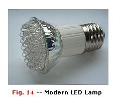
these economical light sources. Christmas tree lights and other festive outdoor lights have brought us the last couple years lots of pleasure and a
very low electricity bill from the hydro company. There are so many other applications today in which the old-fashion incandescent bulbs are replaced
with LEDs, like Christmas Lights for indoor or outdoor use, safety flares, vehicle flashers, tail and signal lights for automobiles, and just the
regular 'LED' lamp for home use (see Fig. 14) and so on.
In summary, LED's have gone from infancy to adolescence and are experiencing some of the most rapid market growth of their lifetime. By using
InGaAlP material with MOCVD as the growth process, combined with efficient delivery of generated light and efficient use of injected current, some of
the brightest, most efficient and most reliable LEDs are now available. This technology together with other novel LED structures will ensure wide
application of LEDs. New developments in the blue spectrum and on white light output will also guarantee the continued increase in applications of
these economical light sources. Christmas tree lights and other festive outdoor lights have brought us the last couple years lots of pleasure and a
very low electricity bill from the hydro company. There are so many other applications today in which the old-fashion incandescent bulbs are replaced
with LEDs, like Christmas Lights for indoor or outdoor use, safety flares, vehicle flashers, tail and signal lights for automobiles, and just the
regular 'LED' lamp for home use (see Fig. 14) and so on.
Hints and Tips
Avoid inadvertent reverse LED connection. Reverse voltages in excess of about 5V will cause permanent damage.
For battery powered equipment (particularly where a number of LED indicators are used) minimal values of forward current should be employed in
order to ensure long battery life. A forward current of 5mA (per LED) will be perfectly adequate in many applications.
Where several LED's are to be used together, they should be connected in series (and not in parallel) in order to ensure equal levels of light output.
Yellow and Green LED generally give less output (for a given forward current) than their standard red counterparts. To maintain an equal light
output when several LED's of different colors are used together, different values of series resistors may be employed. As a rule of thumb, series
resistors for yellow and green LED's slhould be chosen so that they are 10% to 15% lower in vlaue tha tthose used with red LED's (care should, however,
be taken to ensure that operating currents are still within the manfacturer's specified upper limit).
In applications involving low AC voltages, a conventional low-current silicon diode such as the 1N4148 can be wired in parallel with the LED to
provide a simple AC indicator.
Thank you for taking the time to read this Led Tutorial! -Tony van Roon
Copyright & Credits:
Text and examples excerpts taken from "Solid-State Light Sources" by Joseph J. Carr, June 1992, from Popular Electronics
Magazine. Published by Gernsback Publishing (no longer in business). This article has been edited for content by Tony van Roon.
"50 Year history of the LED", by Steve Bush. From "Electronics Weekly" website.
Suggested Reading:
The Led Light
Electronics Tutorials
Wikipedia, Light Emitting Diode
Return to More Tutorials here.
Last updated: October 26, 2010