Home » Circuits
Automatic Air Humidifier
The humidifier circuit is based on a special humidity sensor Type NH-3 from Figaro. Depending on the sensor output, the circuit drives a ventilator that is part of an air humidifying installation. The ventilator is switched on an off by a triac. So as to keep the circuit as simple as possible, the supply voltage and the test voltage are drawn directly from the mains supply. The 240 V mains voltage is converted into an 8.9 V pulsating direct potential by capacitor C1, resistor R1 and zener diode D1. The pulsating voltage is used to drive the sensor.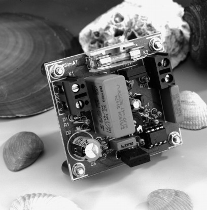 It is also transformed to a 7.5 V supply voltage by D2 and C2. The sensor needs an alternating drive voltage at a level not higher than 1.5 V. This potential is obtained from the pulsating direct voltage by network R2-R3-C3-C4, which removes the direct voltage component and lowers the level to 1.4 V. At the same time, the network functions as a 50 Hz bandpass filter. To ensure that the drive voltage for the sensor does not fall outside the common-mode range of op amp IC2, an offset potential of 3.9 V is applied to the sensor as well as to the voltage reference source of the op amp.
 This potential is provided by zener diode D3. The reference level is set with P1.The op amp is given some hysteresis by R5. When the humidity of the ambient air rises above that corresponding to the level with P1, the output voltage of IC2 is about 6 V. This results in T1 being cut off by D4, whereupon the triac is also disabled. When the humidity drops below that corresponding to the level set with P1, a pulsating potential appears at the output of IC2. This voltage is used to charge capacitor C6.
 The charged capacitor thereupon provides a steady current to the triac. When T1 is cut off for some time, capacitor C6 is discharged via resistor R7. Capacitors C1 and C7 are discharged via R9, so that after the mains has been switched off, no dangerous potential remains at the pins of the mains connector (K1). The humidifier is best built on the PCB shown in Figure 2, which is available ready made (see Readers services pages towards the end of this issue). Bear in mind that parts of the board will carry mains voltage, which makes careful working and the enclosing of the board in a plastic case imperative. The humidifier may be converted into a dehumidifier by interchanging connections 1 and 3 to sensor IC1.
 Parts list
Resistors:
R1 = 470 Ω, 1 W
R2, R3 = 10 kΩ
R4 = 1 kΩ
R5 = 56 kΩ
R6 = 6.8 kΩ
R7 = 4.7 kΩ
R8 = 470 Ω
R9 = 2.2 MΩ
R10 = 39 Ω, 1 W
P1 = 1 kΩ preset
Capacitors:
C1 = 0.47 µF, 250 V a.c.
C2 = 470 µF, 16 V, radial
C3, C4 = 0.33 µF, metallized polyester, 5%
C5 = 0.1 µF, high stability
C6 = 47 µF, 16 V, radial
C7 = 0.047 µF, 250 V a.c.
Semiconductors:
D1 = zener diode, 8.2 V, 1.3 W
D2 = 1N4001
D3 = zener diode, 3.9 V, 500 mW
D4 = zener diode, 2.4 V, 500 mW
T1 = BC557B
Integrated circuits:
IC1 = NH-3 (Figaro)
IC2 = TLC271CP Tri
1 = TLC336T (SGS)
Miscellaneous:
K1, K2 = 2-way terminal block for board mounting, pitch 7.5 mm
F1 = fuse-holder with 630 mA slow fuse