Home » Circuits
Buck-Boost Voltage Converter
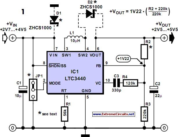
Sometimes it is desired to power a circuit from a battery where the required supply voltage lies within the discharge curve of the battery. If the battery is new, the circuit receives a higher voltage than required, whereas if the battery is towards the end of its life, the voltage will not be high enough. This is where the new LTC 3440 buck/boost voltage converter from Linear Technology (www.linear.com) can help. The switching regulator in Figure 1 converts an input voltage in the range +2.7 V to +4.5 V into an output voltage in the range +2.5 V to +5.5 V using one tiny coil.Circuit diagram:
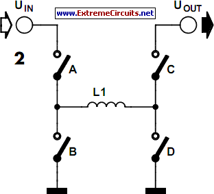
The level of the output voltage is set by the voltage divider formed by R2 and R3. The device switches as necessary between step-up (or ‘boost’) operation when Vin is less than Vout , and step-down (or ‘buck’) operation when Vin is greater than Vout. The maximum available output current is 600mA. The IC contains four MOSFET switches (Figure 2) which can connect the input side of coil L1 either to Vin or to ground, and the output side of L1 either to the output voltage or to ground. In step-up operation switch A is permanently on and switch B permanently off. Switches C and D close alternately, storing energy from the input in the inductor and then releasing it into the output to create an output voltage higher than the input voltage.
Circuit diagram:
In step-down operation switch D is permanently closed and switch C permanently open. Switches A and B close alternately and so create a lower voltage at Vout in proportion to the mark-space ratio of the switch ing signal. L1, together with the output capacitor, form a low-pass filter. If the input and output voltages are approximately the same, the IC switches into a pulse-width modulation mode using all four switches. Resistor R1 sets the switching frequency of the IC, which with the given value is around 1.2 MHz. This allows coil L1 to be very small. A suitable type is the DT1608C-103 from Coilcraft (www.coilcraft.com).
The IC can be shut down using the SHDN/SS input. A ‘soft start’ function can also be implemented by applying a slowly-rising voltage to this pin using an RC network. The MODE pin allows the selection of fixed-frequency operation (MODE connected to ground) or burst mode operation (MODE=Vin). The latter offers higher efficiency (of between 70% and 80%) at currents below 10 mA. At currents of around 100 mA the efficiency rises to over 90 %. A further increase in efficiency can be obtained by fitting the two Schottky diodes shown dotted in the circuit diagram. These operate during the brief period when both active switches are open (break-before-make operation).
Author: Gregor Kleine - Copyright: Elektor July-August 2004


