Home » Circuits
DC Control for Triacs
If a circuit is to switch a mains voltage, a relay is a simple solution in cases where switching times are long and high currents are involved. However, at lower currents, and in particular where rapid switching is required, such as in sound-to-light systems, a relay no longer fills the bill. Electrical isolation is often a requirement, which rules out driving a triac via a transistor. Here we use the MOC3041 optocoupler, which is specially designed for such applications, to drive a power triac. The control circuit therefore remains galvanically isolated from the mains. The internals of the optocoupler are somewhat more complex than appears from the circuit diagram. A special zero-crossing detector circuit in the optocoupler ensures that the connected triac is only triggered when the alternating mains voltage goes through zero.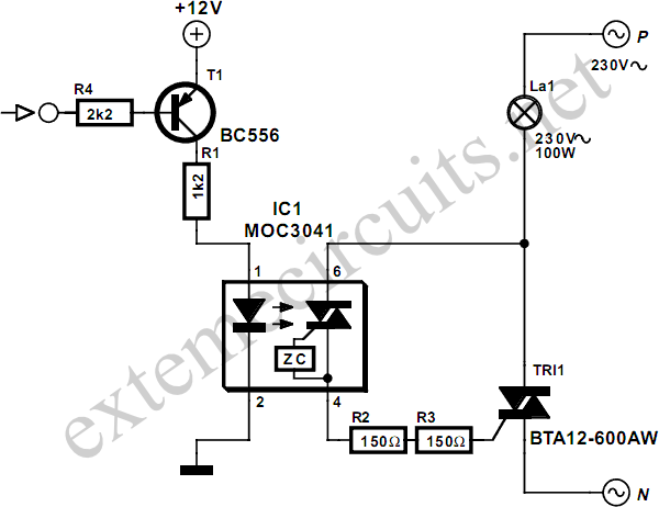 This has the advantage of generating less interference compared to switching the triac at arbitrary phase in a cycle. Indeed, it means that we can dispense with the suppressor choke at the output that would otherwise be necessary. If very brief pulses are likely to be present at the input to the opto-coupler, a 220 nF capacitor should be connected between the input of the circuit and the emitter of T1 to lengthen the drive pulses. This ensures that the triac will be triggered even with very short input pulses, which might otherwise miss the zero-crossing point of the mains waveform. The triac should be an AW-suffix type. These types are less sensitive, but have higher dv/dt and di/dt specifications. The gate resistance must be constructed from two resistors connected in series, since normal resistors are not suitable for direct use with mains voltages. It is also necessary to exercise care around the opto-coupler. In order to guarantee Class II isolation the solder pads on the input and output sides must be separated by at least 6 mm. The leads may therefore need to be bent outwards when soldering.