Home » Circuits
Driver For 20 LEDs
If we wish to use a step-up switching regulator to run several LEDs from, for example, a 3 V battery, we find that the maximum usable mark-space ratio limits us to driving just a few LEDs in series. If we have seven white LEDs in series the total forward voltage will be about 7 times 3.4 V, or 23.8 V, requiring a mark-space ratio of around 90 %. This is the upper limit for many switching regulators. If we want to drive more LEDs, we must divide them into a number of parallel strings, for which the regulator will of course have to supply the necessary current.There are various ways to drive a parallel array of series-connected LEDs. The simplest approach is to wire a number of chains, each consisting of the same number of LEDs and a series resistor, in parallel, hoping that the total forward voltage of the LEDs in each chain is approximately the same. We can sense the current in a single chain using a sense resistor R, and thereby deliver the same current to the other chains as well. Unfortunately, the assumption that the total forward voltage of the LEDs in each chain is the same is not always borne out in practice.
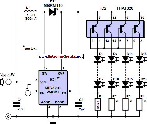
To get around this problem we can use a multi-way current mirror, which can, for example, be constructed using a bipolar transistor array such as the THAT320. The circuit shows a type MIC2291 PWM step-up LED driver from Micrel driving a four-by-five LED array. This arrangement leaves the device a little headroom in terms of mark-space ratio and total power. The voltage at the output will be at most 18 V in normal operation. A particular advantage of the MIC2291 in this circuit is its low feedback voltage of 95 mV, which makes for a correspondingly high efficiency. The current in each chain is calculated as follows:
LED = 95 mV/R1 = 95 mV/4.7R = 20 mA.
The circuit can operated from voltages from 3 V to 10 V. If fewer than five LEDs are used in each chain, or if LEDs with a lower forward voltage are used, the battery voltage may need to be reduced: it must be lower than the total forward voltage drop of the chain. Otherwise, as with any boost converter, an unregulated and potentially damaging current will flow continuously through the LEDs. Also, if the chains contain different numbers of LEDs or if different colour LEDs are used, care must be taken to ensure that the sum of the LED forward voltages is greatest in the first (regulated) chain.
Circuit diagram:
The EN input allows the LED array to be turned on (EN greater than 1.5 V) or off (EN less than 0.4 V), or dimmed using a PWM signal. An alternative (analogue) dimming technique is also described in the MIC2291 data sheet. The Schottky diode must be a fast-switching type with a low capacitance and low voltage drop, such as the MBRM140 or SS14. Ceramic capacitors C1 and C2 should be XSR or X7R types with a suitable working voltage. The 10 µH coil must have a rated current of at least 600 mA without saturating, and it should also have as low a resistance as possible.
And of course, when building an LED driver circuit with a switching speed of 1.2o the layout and construction of switching regulators should be observed. The MIC2291-34BML and its lead-free counterpart the MIC2291-34YML in a 2 mm by 2 mm MLF package have a 34V overvoltage protection circuit (and an extra OVP pin); the MIC2291YDS in a 5-pin SOT-23 package is a low-cost ver- sion without overvoltage protection. Since we would otherwise have to implement this protection externally, the MLF type is preferred.
Internet links
MIC2291 data sheet: www.micrel.com/_PDF/mic2291.pdf
Application example: www.micrel.com/_PDF/App-Hints/ah-59.pdf
THAT320: www.thatcorp.com/300desc.html
Author: Eberhard Haug - Copyright: Elektor Electronics

