Home » Circuits
DTMF Receiver IC MT8870 Tester
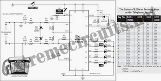
Today, most telephone equipment use a DTMF receiver IC. One common DTMF receiver IC is the Motorola MT8870 that is widely used in electronic communications circuits. The MT8870 is an 18-pin IC. It is used in telephones and a variety of other applications. When a proper output is not obtained in projects using this IC, engineers or technicians need to test this IC separately. A quick testing of this IC could save a lot of time in research labs and manufacturing industries of communication instruments. Here’s a small and handy tester circuit for the DTMF IC. It can be assembled on a multipurpose PCB with an 18-pin IC base. One can also test the IC on a simple breadboard. For optimum working of telephone equipment, the DTMF receiver must be designed to recognise a valid tone pair greater than 40 ms in duration and to accept successive digit tone-pairs that are greater than 40 ms apart.However, for other applications like remote controls and radio communications, the tone duration may differ due to noise considerations. Therefore, by adding an extra resistor and steering diode the tone duration can be set to different values. The circuit is configured in balanced-line mode. To reject common-mode noise signals, a balanced differential amplifier input is used. The circuit also provides an excellent bridging interface across a properly terminated telephone line. Transient protection may be achieved by splitting the input resistors and inserting zener diodes (ZD1 and ZD2) to achieve voltage clamping. This allows the transient energy to be dissipated in the resistors and diodes, and limits the maximum voltage that may appear at the inputs. Whenever you press any key on your local telephone keypad, the delayed steering (Std) output of the IC goes high on receiving the tone-pair, causing LED5 (connected to pin 15 of IC via resistor R15) to glow.
 It will be high for a duration depending on the values of capacitor and resistors at pins 16 and 17. The optional circuit shown within dotted line is used for guard time adjustment. The LEDs connected via resistors R11 to R14 at pins 11 through 14, respectively, indicate the output of the IC. The tone-pair DTMF (dual-tone multi-frequency) generated by pressing the telephone button is converted into binary values internally in the IC. The binary values are indicated by glowing of LEDs at the output pins of the IC. LED1 represents the lowest significant bit (LSB) and LED4 represents the most significant bit (MSB). So, when you dial a number, say, 5, LED1 and LED3 will glow, which is equal to 0101. Similarly, for every other number dialled on your telephone, the corresponding LEDs will glow. Thus, a non-defective IC should indicate proper binary values corresponding to the decimal number pressed on your telephone keypad.
To test the DTMF IC 8870/KT3170, proceed as follows:
- Connect local telephone and the circuit in parallel to the same telephone line.
- Switch on S1. (Switch on auxiliary switch S2 only if keys A, B, C, and D are to be used.)
- Now push key ‘*’ to generate DTMF tone.
- Push any decimal key from the telephone keypad.
- Observe the equivalent binary as shown in the table.
- If the binary number implied by glowing of LED1 to LED4 is equivalent to the pressed key number (decimal/A, B, C, or D), the DTMF IC 8870 is correct.
