Home » Circuits
Dual Power Amplifier Using TDA7293 MOSFET IC
As readers will know, there are already several power amplifier projects, two using IC power amps (aka power opamps). Both have been popular, and this project is not designed to replace either of them. However, it is significantly smaller than the others, so it makes building a multiple amp unit somewhat easier because the space demand is much lower. It's quite simple to include 4 amps (two boards) into a small space, but be aware that good heatsinking is essential if you expect to run these amps at significant power levels.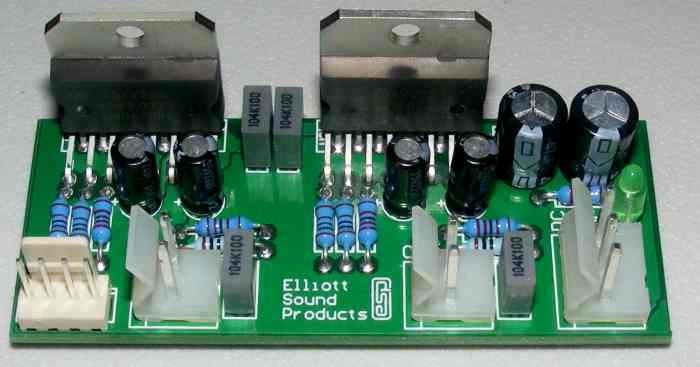 Photo of Completed P127 Board
This particular project has been planned for a long time, but for some reason I never got around to completing the board or the project description. This is now rectified, and it's ready to "rock and roll". The board is very small - only 77 x 31mm, so getting it into tight spaces is easy ... provided adequate heatsinking is available of course.
Description
The TDA7293 has a bewildering number of options, even allowing you to add a second power stage (in another IC) in parallel with the main one. This improves power into low impedance loads, but is a rather expensive way to get a relatively small power increase. It also features muting and standby functions, although I've elected not to use these.
The schematic is shown in Figure 1, and is based on the PCB version. All unnecessary functions have been disabled, so it functions as a perfectly normal power amplifier. While the board is designed to take two TDA7293 ICs, it can naturally be operated with only one, and the PCB is small enough so that this is not an inconvenience. A LED is included to indicate that power is available, and because of the low current this will typically be a high brightness type.
 Figure 1 - Schematic of Power Amplifier (One Channel Shown)
I normally use a gain of 23 (27dB) for all amplifiers, and the TDA7293 is specified for a minimum gain of 26dB, below which it may oscillate. Although this is only a small margin, tests so far indicate that the amp is completely stable. If you wish, you may increase the gain to 28 (29dB) to give a bit more safety margin. To do this, just change the input and feedback resistors (R3A/B and R4A/B) from 22k to 27k.
The circuit is conventional, and is very simple because all additional internal functions are unused. The LED is optional, and if you don't think you'll need it, it may be omitted, along with series resistor R3. All connections can be made with plugs and sockets, or hard wired. In most cases, I expect that hard wiring will be the most common, as the connectors are a pain to wire, and add unnecessary cost as well as reduce reliability.
The TDA7293 specifications might lead you to believe that it can use supply voltages of up to ±50V. With zero input signal (and therefore no output) it might, but I don't recommend anything greater than ±35V if 4 ohm loads are expected, although ±42V will be fine if you can provide good heatsinking. In general, the lower supply voltage is more than acceptable for 99% of all applications, and higher voltages should not be used unless there is no choice. Naturally, if you can afford to lose a few ICs to experiments, then go for the 42V supplies (obtained from a 30+30V transformer).
Construction
Because of the pin spacings, these ICs are extremely awkward to use without a PCB. Consequently, I recommend that you use the ESP board because it makes building the amplifier very simple. The PCBs are double sided with plated-through holes, so are very unforgiving of mistakes unless you have a good solder sucker. The best way to remove parts from a double sided board is to cut the pins off the component, then remove each pin fragment individually. This is obviously not something you'd wish to do if a power amp IC were installed incorrectly, since it will be unusable afterwards.
 Figure 2 - TDA7293V Pinouts
The diagram above shows the pinouts for the TDA7293V (the "V" means vertical mounting). Soldering the ICs must be left until last. Mount the ICs on your heatsink temporarily, and slide the PCB over the pins. Make sure that all pins go through their holes, and that there is no strain on the ICs that may try to left the edge off the heatsink. When ICs and PCB are straight and aligned, carefully solder at least 4 pins on each IC to hold them in place. The remaining pins can then be soldered. Remember, if you mess up the alignment at this point in construction, it can be extremely difficult to fix, so take your time to ensure there are no mistakes.
This amplifier must not be connected to a preamp that does not have an output coupling capacitor. Even though there is a cap in the feedback circuit, it can still pass DC because there is no input cap on the PCB. I normally include an input cap, but the goal of this board was to allow it to fit into the smallest space possible, and the available board space is not enough to include another capacitor. A volume control (typically 10k log/ audio taper) may be connected in the input circuit if desired.
Note that the metal tab of the TDA7293 is connected to the -Ve supply, so must be insulated from the heatsink. The more care you take with the mounting arrangement, the better. While you can use a screw through an insulating bush and a piece of mica to insulate the tab, a better alternative is to use a clamping bar of some kind. How you go about this depends a lot on your home workshop tools and abilities, but one arrangement I've found highly satisfactory is a suitable length of 6.25mm square solid steel bar. This is very strong, and allows good pressure on the mica (or Kapton) for maximum heat transfer. Naturally, heatsink compound is absolutely essential.
Do not be tempted to use silicone insulation washers unless you are using the amp at very low supply voltages (no more than ±25V). Its thermal transfer characteristics are not good enough to allow the amp to produce more than about 10 - 20W of music, and even that can be taxing for silicone washers. The amp will shut down if it overheats, but that curtails one's listening enjoyment until it cools down again.
Power Supply
A suitable power supply is shown below, and is completely unremarkable in all respects. The transformer may be a conventional (E-I) laminated type or a toroid. The latter has the advantage of lower leakage flux, so will tend to inject less noise into the chassis and wiring. Conventional transformers are usually perfectly alright though, provided you take care with the mounting location.
The bridge rectifier should be a 35A 400V type, as they are cheap, readily available and extremely rugged. Electrolytic capacitors should be rated at 50V. The cap connected across the transformer secondary (C4) should be rated at 275V AC (X Class), although a 630V DC cap will also work. This capacitor reduces "conducted emissions", namely the switching transients created by the diodes that are coupled through the transformer onto the mains supply. The power supply will work without this cap, and will most likely pass CE and C-Tick tests as well, but for the small added cost you have a bit of extra peace of mind as regards mains noise.
 Figure 3 - Suggested Power Supply
The supply shown includes a "loop breaker", which is intended to prevent earth/ ground loops to prevent hum when systems are interconnected. Please be aware that it may not be legal to install this circuit in some countries. The diodes must be high current types - preferably rated at no less than 3A (1N5401 or similar). The loop breaker works by allowing you to have the chassis earthed as required in most countries, but lets the internal electronics "float", isolated from the mains earth by the 10 ohm resistor. RF noise is bypassed by the 100nF cap, and if a primary to secondary fault develops in the transformer, the fault current will be bypassed to earth via the diodes. If the fault persists and the internal fuse (or main power circuit breaker) hasn't opened, one or both diodes will fail. Semiconductor devices fail short-circuit, so fault current is connected directly to safety earth.
Be very careful when first applying mains power to the supply. Check all wiring thoroughly, verify that all mains connections are protected from accidental contact. If available, use a Variac, otherwise use a standard 100W incandescent lamp in series with the mains. This will limit the current to a safe value if there is a major fault.
When the loop breaker is used, all input and output connectors must be insulated from the chassis, or the loop breaker is bypassed and will do nothing useful. The body of a level pot (if used) can be connected to chassis, because the pot internals are insulated from the body, mounting thread and shaft.
Note that the DC ground for the amplifiers must come from the physical centre tap between the two filter caps. This should be a very solid connection (heavy gauge wire or a copper plate), with the transformer centre tap connected to one side, and the amplifier earth connections from the other. DC must be taken from the capacitors - never from the bridge rectifier.
The order of the fuse and power switch is arbitrary - they can be in any order, and in many cases the order is determined by the physical wiring of the IEC connector if a fused type is used. With a fused IEC connector, the fuse is before the switch and it cannot be removed while the mains lead is inserted.
I have shown a 2A slow-blow fuse, but this depends on the size and type of transformer and your mains supply voltage. Some manufacturers give a recommended fuse rating, others don't. The fuse shown is suitable for a 150VA transformer at 230V AC, and is deliberately oversized to ensure that it will not be subject to nuisance blowing due to transformer inrush current. A 2A fuse will fail almost instantly if there is a major fault.
Make sure that the mains earth (ground) is securely connected to guarantee a low resistance connection that cannot loosen or come free under any circumstances. The accepted method varies from one country to the next, and the earth connection must be made to the standards that apply in your country.
WARNING: This power supply circuit requires experience with mains wiring. Do not attempt construction unless experienced, capable and suitably qualified if this is a requirement where you live. Death or serious injury may result from incorrect wiring.
Testing
Never attempt to operate the amplifier without the TDA7293 ICs attached to a heatsink!
Connect to a suitable power supply - remember that the supply earth (ground) must be connected! When powering up for the first time, use 100 ohm 5W "safety" resistors in series with each supply to limit the current if you have made a mistake in the wiring. If available, use a variable bench supply - you don't need much current to test operation, and around 500mA is more than enough. If using a current limited bench supply, the safety resistors can be omitted. Do not connect a speaker to the amplifier at this stage!
If using a normal power supply for the amp tests, apply power (±35V via the safety resistors) and verify that the current is no more than 60mA or so - about 6V across each 100 ohm resistor. No load current can vary, so don't panic if you measure a little more or less. Verify that the DC voltage at both outputs is less than 100mV. Using another 100 ohm resistor in series with a small speaker, or an oscilloscope, apply a sinewave signal at about 400Hz to the input and watch (or listen) for signal. The signal level needs to be adjusted to ensure the amp isn't clipping, and the waveform should be clean, with no evidence of parasitic oscillation or audible distortion.
If everything tests out as described, wire the amplifier directly to the power supply and finish off any internal wiring in the amp. Once complete, it's ready to use.