Home » Circuits
Electronic Telephone Ringer
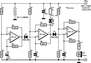
This circuit produces a ringing sound similar to that made by more recent telephones. It consists of three almost identical oscillators connected in a chain, each generating a squarewave signal. The frequency of each oscillator depends on the RC combination: R4 and C1 around IC1.A, R8 and C2 around IC1.B and R12 and C3 around IC3.C. The pairs of 100 kΩ resistors divide the asymmetric power supply voltage (between 5 V and 30 V) so that, in conjunction with the 100 kΩ feedback resistors (R3, R7 and R11) either one third or two thirds of the supply voltage will be present at the non-inverting inputs to the opamps. The voltage across the capacitor therefore oscillates in a triangle wave between these two values.
The first oscillator is free-running at a frequency of approximately 1/3 Hz. Only when its output is high, and D1 stops conducting, can the second oscillator run. The frequency of the second oscillator is about 13 Hz, and optional LED D3 flashes when it is running. When the output of the second oscillator is low, the third is allowed to run. The frequency of the third oscillator is around 1 kHz, and this is the tone that is produced. The second oscillator is not absolutely necessary: its function is just to add a little modulation to the 1 kHz tone. A piezo sounder is connected to the output of the third oscillator to convert the electrical signal into an acoustic one. The current consumption of the circuit is just under 1mA with a 5V power supply, rising to about 1.65mA with a supply voltage of 15 V.
Author: L. Libertin
Copyright: Elektor Electronics
Copyright: Elektor Electronics
