Home » Circuits
Frequency Multiplier For LF Measurements
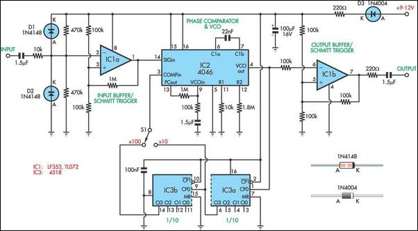
When designing bass reflex loudspeaker cabinets, it is necessary to measure the resonance of the speaker to an accuracy of about 1%. To do this, you need an audio oscillator and a frequency counter. However, the typical accuracy and resolution of a frequency counter when measuring frequencies below 50Hz can lead to errors of several percent. The solution to this problem is to use a frequency multiplier and the circuit presented here can be switched to multiply by 10 or 100. It uses a 4046 phase locked loop (PLL) and a 4518 connected as a dual divide-by-10 counter. As shown, the oscillator signal is fed into the comparator formed by IC1a and its output drives the SIGin input, pin 14, of the 4046 PLL (IC2).Circuit diagram:
The PLL's output is fed to IC3 and divided by 10 or 100, depending on the setting of switch S1. The divided signal is then fed to the COMPin input (pin 3) of IC2. In this way, the PLL is forced to multiply the input frequency by 10 or 100 and this multiplied frequency can be read out with much improved accuracy by a typical digital frequency meter. However, you must then divide the displayed reading by the selected multiplication ratio to get the true frequency. The limitation in this circuit is that the 4046 can only run up to 20kHz so that the input frequency is limited to 200Hz or 2kHz, depending on the multiplication ratio. This is quite adequate for measuring bass reflex cabinets.
Author: J. Begg - Copyright: Silicon Chip Electronics

