Home » Circuits
Gym Agility: A Simple Strategy Game
This simple circuit is a two-person game of strategy and speed - and potentially, agility and athletic fitness. Each player has a row of four LEDs before him/her. Beside each LED, there is a pushbutton which, when pressed, lights up the corresponding LED. The aim of the game is for a player to illuminate all four of their LEDs in a row, in which case the circuit declares a winner. However, there is a catch. As soon as you light one of your own LEDs, the other player's corresponding LED goes out - and vice versa.The game begins by giving each player two illuminated LEDs. Consider now that this game is scaled up and used in a gym. If the LEDs in the circuit are directly replaced with N-channel power MOSFETs, then 12V globes can be illuminated (a MOSFET's gate is wired in place of a LED's anode, the source goes to negative, and the load is wired between the drain and positive). If four large pushbuttons are mounted on one wall and four on another, this could become a game of agility - if not a physical tussle to keep the other player away from critical push-buttons.
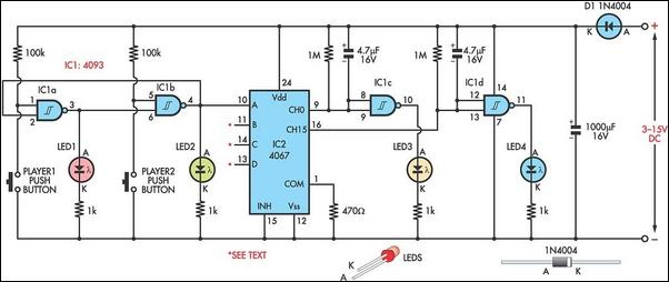
Circuit diagram:
Here's how the circuit works:
Schmitt NAND gate IC1a and IC1b (4093) form a simple bistable latch. When one output (pin 3) goes "high", the other output (pin 4) goes "low" and vice versa. The main advantage of using a bistable latch (as opposed to a flipflop) is that it does not suffer from switch bounce. Four such bistable latches are fed to inputs A-D of IC2. However, for the sake of simplicity, only one of these is shown; ie, IC1a-IC1b. We now need to identify when all four bistable latches go either "high" or "low".
This is done using IC2, a 4067 16-channel multiplexer. When inputs A-D are all "low" (binary 0000), this opens decimal channel 0. Conversely, when all are "high" (binary 1111), this opens decimal channel 15. Channels 0 and 15 thus trigger a win for one side or the other, by taking pins 9 or 16 of IC2 "low". Finally, if the game is quite hectic, a win might only last for a fraction of a second before it is lost again. Therefore, IC1c and IC1d are wired as timers, which do not permit any further play until a win has been reported for one or two seconds - either via LED3 or LED4. During this time, however, the players' buttons may be pressed to reset the game to two LEDs all.
Author: Thomas Scarborough - Copyright: Silicon Chip Electronics Magazine

