Home » Circuits
High Current Low-Dropout Voltage Regulator
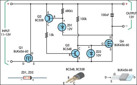
This circuit was designed to allow a laptop computer to be powered from a solar power setup. The computer requires 12V at 3.3A. The circuit is a linear regulator with Mosfet Q4 as the series pass device. A 100kO resistor provides Q4 with a positive gate-source voltage. Any tendency for the output voltage to exceed ZD1's voltage causes Q2 to turn on. This turns on Q3 which reduces Q4's gate voltage and thus reduces the output voltage. Note that Q2's base-emitter voltage stabilizes at about 0.35V. This combined with the zener voltage gives an output of 12.4V. If a more precise output is required, first select ZD1 so that its voltage rating is at least 0.4V less than the required output voltage.Circuit diagram:
You can then "trim" to the required output voltage by installing a resistor in series with ZD1. Q2's base-emitter voltage and the 680W base resistor set the current through ZD1 to 0.5mA. This means that the output voltage will be boosted by 0.1V for each 200O of resistance in series with ZD1. Zener diode ZD2 ensures that Q4's maximum rated gate-source voltage is not exceeded. Mosfet Q1 provides reverse polarity protection. Note that Q4 requires a heatsink since it will dissipate about 10W under worst-case conditions. No heatsink is required for Q1. At 3.3A, the regulator reduces the output voltage by just 0.2V. This can be further reduced by paralleling Q1 & Q4 with additional Mosfets.
Author: Andrew Partridge - Copyright: Silicon Chip

