Home » Circuits
HQ Notch Filter Without Close-Tolerance components
A notch for a narrow frequency band of a few per cent or even less normally requires close-tolerance components. At least, that’s what we thought until we came across a special opamp IC from Maxim.In filters with steep slopes, the component tolerances will interact in the complex frequency response. This effect rules out the use of standard tolerance components if any useful result is to be achieved. The circuit shown here relocates the issue of the value-sensitive resistors that determine the filter response from ‘visible’ resistors to ready available integrated circuits which also make the PCB layout for the filter much simpler. The operational amplifiers we’ve in mind contain laser-trimmed resistors that maintain their nominal value within 1‰ or less. For the same accuracy, the effort that goes into matching individual precision resistors would be far more costly and time consuming. The desired notch (rejection) frequency is easily calculated for both R-C sections shown in Figure 1.
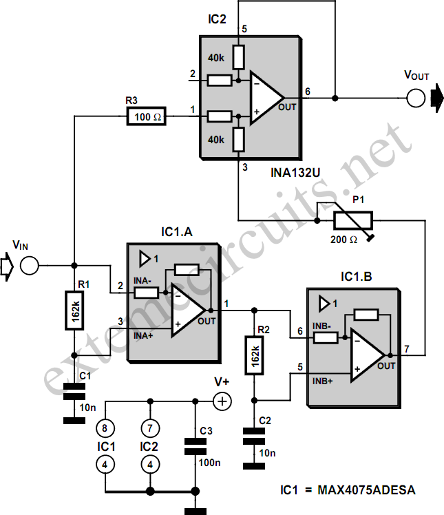 Figure 1. Special opamps incorporating laser-trimmed resistors.
The circuit separates the amplitude and frequency domains using two frequency-determining R-C networks and two level-determining feedback networks of summing amplifier IC2, which suppresses the frequency component to be eliminated from the input signal by simple phase shifting. IC1 contains two operational amplifiers complete with a feedback network. The MAX4075 is available in no fewer than 54 different gain specifications ranging from 0.25 V/V to 100 V/V, or +1.25 V/V to 101 V/V when non-inverting. The suffix AD indicates that we are employing the inverting version here (G = –1).
These ICs operate as all-pass filters producing a phase shift of exactly 180 degrees at the roll-off frequency f0. The integrated amplifier resistors can be trusted to introduce a gain variation of less than 0.1 %. They are responsible for the signal level (at the notch frequency) which is added to the input signal by IC2 by a summing operation. However, they do not affect the notch frequency proper — that is the domain of the two external R-C sections which, in turn, do not affect the degree of signal suppression. In general, SMDs (surface mount devices) have smaller production tolerance than their leaded counter-parts. Because the two ICs in this circuit are only available in an 8-pin SOIC enclosure anyway, it seems logical to employ SMDs in the rest of the circuit as well. Preset P1 allows the filter to be adjusted for maximum rejection of the unwanted frequency component.
 Figure 2. This deep notch is within reach using just 5%-tolerance resistors and 20%-tolerance capacitors.
Using standard-tolerance resistors for R1 and R2 (i.e., 1%, 0806 style) and 10%-tolerance capacitors for C1 and C2 (X7R ceramic) an amount of rejection better than that shown in Figure 2 may be achieved. The notch frequency proper may be defined more accurately by the use of selected R-C sections. Pin 3 of IC2 receives a signal that’s been 90-degrees phase shifted twice at the notch frequency, while pin 1 is fed with the input signal. These two signals are added by way of the two on-chip resistors. IC2 is a differential precision operational amplifier containing precision resistor networks trimmed to an error not exceeding ±0.2‰. Here, it is configured as a modified summing amplifier with its inverting input, pin 2, left open.
 For frequencies considerably lower than the resonance frequency f0 = 1 / (2 π R C) the capacitors present a high impedance, preventing the inverting voltage followers from phase-shifting the signal. At higher frequencies than f0, each inverting voltage follower shifts its input signal by 180 degrees, producing a total shift of 360 degrees which (electrically) equals 0 degrees. The phases of each all-pass filter behave like a simple R-C pole, hence shift the signal at the resonance frequency by 90 degrees each. The three precision amplifier ICs can handle signals up to 100 kHz at remarkably low distortion. The supply voltage may be anything between 2.7 V and 5.5V. Current consumption will be of the order of 250µA.