Home » Circuits
Improved Vibrating Battery Tester
Many blind and deaf-blind people use portable electronic devices to assist their everyday lives but it is difficult for them to test the batteries used in that equipment. Talking voltmeters are available for the blind but there is no commercially available equivalent usable by deaf-blind persons. This device enables blind, deaf-blind and sighted people to test batteries. It will test AAA, AA, C and D cells, as well as 9V "transistor" batteries. All rechargeable and non-rechargeable cell types are supported. The circuit needs no calibration. To use the tester, turn potentio-meter VR1 fully counter-clockwise and then connect the battery to be tested to the appropriate set of test terminals. If the battery has any usable charge, the pager motor in the tester will immediately vibrate.VR1 is then slowly rotated in a clockwise direction just far enough to stop the vibration. The position of VR1 then indicates the loaded voltage of the battery on a scale of 1-1.5V (if the battery is connected to the 1.5V test terminals) or 6-9V (if the battery is connected to the 9V test terminals). A regulated +5.1V rail is generated from the battery under test with the aid of zener diode ZD1. For 9V tests, a 150O resistor limits the zener current, while diode D2 protects the circuit from reverse polarity battery connection. For 1.5V tests, a blocking oscillator formed by Q1, Q2 and L1 steps up the battery voltage before it is applied to the regulator. This configuration works reliably with inputs down to below 0.9V. The output of the oscillator is rectified by D1 and smoothed by the 33µF capacitor.
The circuit has to survive reverse connection of the battery under test. This creates a problem, because the LM393 cannot withstand a voltage more negative than -0.3V at its inputs. Diodes D1 and D2 indirectly protect the non-inverting inputs from negative voltages but series diodes cannot be used to protect the inverting inputs because of the unpredictable voltage drop they introduce. The solution used is to shunt negative voltages at the 1.5V test terminals with diode D3 in conjunction a 1kO resistor (R1). D3 limits the voltage at its cathode to about -0.7V, while resistors R2-R4 divide this by three to give no less than -0.23V at the inverting input (pin 2) of IC1a. When the battery is connected the right way around, D3 is reverse-biased and R1-R4 form a voltage divider that applies a quarter of the battery voltage to IC1a’s inverting input.
Circuit diagram:
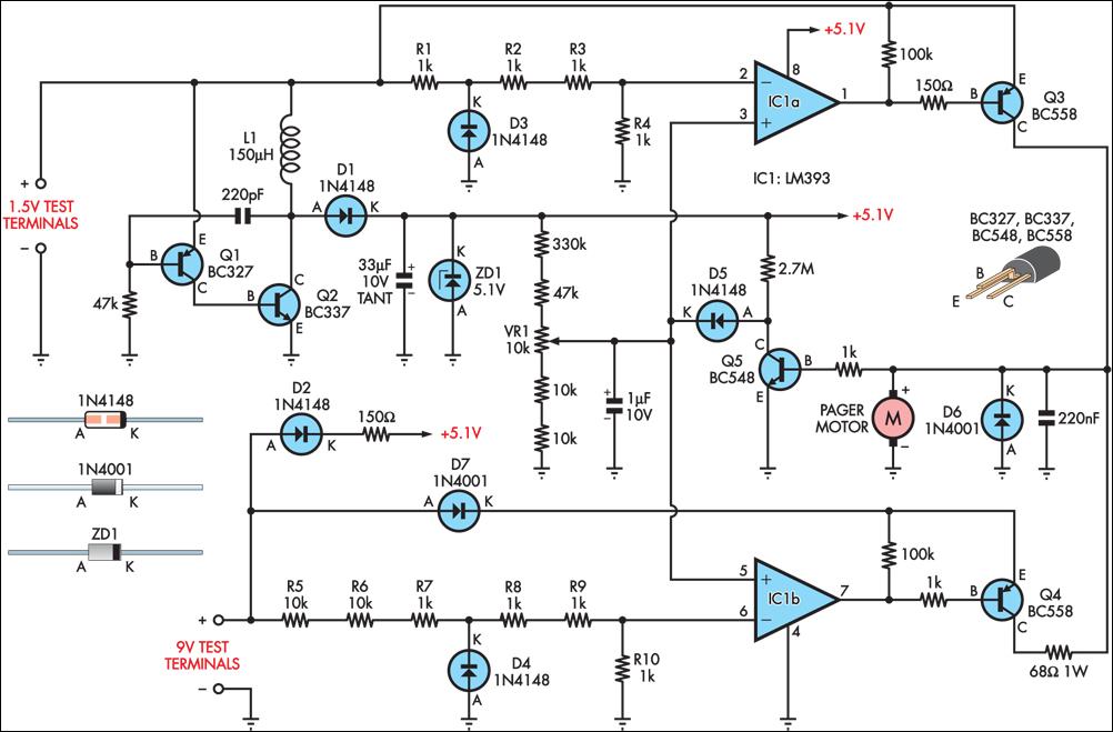
Similarly, D4 and R5-R10 protect the inverting input (pin 6) of IC1b from reverse-connected batteries at the 9V test terminals. However, in this case only 1/24th of the battery voltage appears at IC1b’s inverting input. Battery voltages in the range 1-1.5V at the 1.5V test terminals will therefore produce 0.25-0.375V at the inverting input of IC1a, while battery voltages in the range 6-9V at the 9V test terminals will produce 0.25-0.375V at the inverting input of IC1b. Potentiometer VR1 forms part of a voltage divider used to generate a comparison voltage that is variable over the same 0.25-0.375V range. This is applied to the non-inverting inputs of both IC1a and IC1b. When the sampled battery voltage exceeds this comparison voltage, the respective comparator output swings low, switching on Q3/Q4 to energise the pager motor.
The 68O resistor in the collector circuit of Q4 ensures that higher battery voltages do not overdrive the motor. When testing an earlier version of this circuit with batteries that have high internal impedance, it was found that when VR1 was advanced to the indicating point, the pager motor slowed down rather than switched off. This occurred due to a rebound in battery voltage at motor switch-off, which in turn caused the circuit to immediately switch the motor back on again. To counteract this effect, a small amount of positive feedback is applied around the comparators when the motor switches off. The feedback is disabled while the motor is running so that the indicating point of VR1 is not affected. This works as follows: when the motor is running, Q5 is conducting and D5 is reverse biased, so the comparison voltage at the non-inverting inputs of the comparators is not affected.
If the motor stops running, Q5 switches off and the 2.7MO resistor pulls the comparison voltage higher via D5 to ensure that the resulting battery voltage rebound does not restart the motor. Finally, diode D7 prevents reverse breakdown of Q4 in case of reverse battery connection at the 9V terminals. There is no need for a similar diode in the 1.5V part of the circuit because 1.5V is well below the reverse breakdown voltage of Q3. The prototype used "Magtrix" magnetic connectors on short flexible leads as the 1.5V test terminals. These allow the connection of AAA, AA, C and D cells but are arranged so that they cannot be brought closely together enough to connect 9V types. Unfortunately, magnetic connectors cannot be used for the 9V test terminals because some brands of 9V batteries have non-magnetic terminals. A conventional 9V battery snap can be used instead. For blind people, the knob on VR1 should be pointer-shaped (eg, DSE P-7102) so that the degree of rotation can be easily assessed by touch.
Author: Andrew Partridge
Copyright: Silicon Chip Electronics
Copyright: Silicon Chip Electronics