Home » Circuits
Input Impedance Booster Circuit Diagram
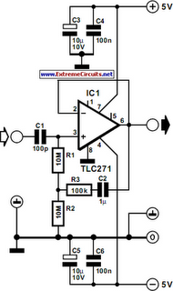
The input impedance of a.c.-coupled op amp circuits depends almost entirely on the resistance that sets the d.c. operating point. If CMOS op amps are used, the input is high, in current op amps up to 10 MΩ. If a higher value is needed, a bootstrap may be used, which enables the input impedance to be boosted artificially to a very high value. In the diagram, resistors R1 plus R2 form the resistance that sets the d.c. operating point for opamp IC1. If no other actions were taken, the input impedance would be about 20 MΩ. However, part of the input signal is fed back in phase, so that the alternating current through R1 is smaller. The input impedance, Zin, is then: Zin=(R2+R3)/R3)(R1+R2). With component values as specified, Zin has a value of about 1GΩ. The circuit draws a current of about 3 mA.Circuit diagram:

