Home » Circuits
Isolated 1-Hz Clock
One of the author’s physics projects required an accurate 1-Hz (seconds) clock signal. Unfortunately, precision 10-MHz quartz crystals are expensive, while another problem was found in the inability of most common or garden 40xx CMOS logic chips to work at such a high frequency. However, a typical CMOS counter like the 4017 has such a high input resistance that its clock input has ‘radio’ properties. The effect is exploited here to convert the stray magnetic field picked up from a mains transformer into a clock signal. Here, the signal is induced in a short piece of wire (approx. 5 cm) connected to the clock input of a CD4017 decade counter for division by 10.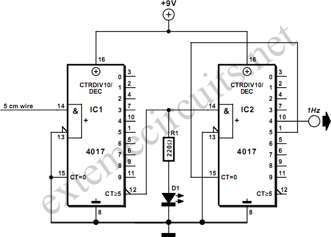
The resulting 5-Hz signal is then divided by 5 by a second 4017 (IC2) to give an output of 1 Hz. LED D1 flashes to indicate the presence of a sufficiently strong magnetic field. The pickup wire should be placed close to the mains transformer, without compromising electrical safety. Always use the greatest distance at which a clock signal is reliably generated. For 1-Hz output from 60-Hz power systems, use output 6 of IC2 (pin 5).