Home » Circuits
LED Flasher
The idea behind this economical flashing LED indicator is very simple: it uses a very low frequency oscillator to drive two LEDs. As can be seen in the circuit diagram, the LEDs are connected in anti-parallel. At every change in level there will only be a current flow for a short time, due to the large capacitor (C3) that is connected in series with D1 and D2. When C3 is charging D1 lights up and when it is discharging D2 lights up. The current through the LEDs is limited by R4. When the circuit is switched on the peak current is determined by R4 and for a red LED will be just over 7 mA: (5–1.6) / 470 = 7.2 mA. This value has been chosen because it is the maximum safe current for certain types of low-current LEDs.When the circuit is in operation the (dis)charging of C1 determines the maximum current. The electrolytic has a minimum voltage remaining which is equal to the LED voltage, causing the pulses to be smaller than the very first pulse: (5 – 2 × 1.6) / 470 = 3.8 mA peak. If one LED is sufficient then you can replace either D1 or D2 with a Schottky diode; the pulse through the remaining LED then becomes slightly larger. The use of two LEDs has the advantage that the discharge current of C3 is also used by the indicator, which makes the circuit more efficient. The oscillator can of course be replaced by a different type, for example the classic Schmitt-trigger/inverter type using a 74HC14 and RC network.
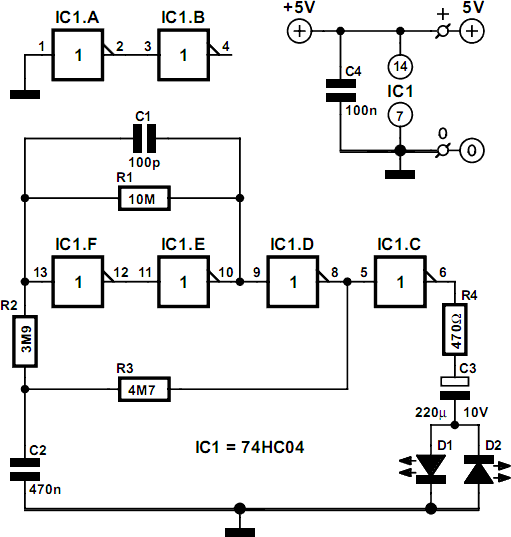
The version used here has the advantage of offering a better stability. C1 makes IC1f switch faster. The resistors have been made as large as possible, so the adjustment of the flash frequency is best done by varying the value of C2. The period with the component values given is about 6 seconds, so a LED will flash every 3 seconds. The current consumption is determined mainly by IC1f, since this is almost working as a linear amplifier. The circuit doesn’t draw more than about 1.3 mA in total. The LEDs used should preferably be red ‘low-current’ or ‘high-efficiency’ types. The current pulses will then be slightly larger and the efficiency of red LEDs is still better than that of green or yellow ones.