Home » Circuits
LED or Lamp Pulsar Circuit
Astonishing effect 4.5V supplyThis circuit operates a LED in pulsing mode, i.e. the LED goes from off state, lights up gradually, then dims gradually, etc. This operation mode is obtained by a triangular wave generator formed by two op-amps contained in a very cheap 8 pin DIL case IC. Q1 ensures current buffering, in order to obtain a better load drive. R4 & C1 are the timing components: using the values shown in the parts list, the total period is about 4 seconds.
Circuit diagram:
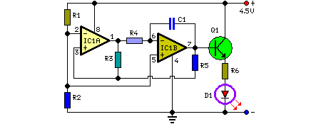
Parts:
R1 = 4.7K
R2 = 4.7K
R3 = 22K
R4 = 2.2M
R5 = 10K
R6 = 47R
C1 = 1µF-63V
Q1 = BC337
D1 = Red Led
IC1 = LM358
Notes:
- The most satisfying results are obtained adopting for R4 a value ranging from 220K to 4M7.
- Adopting for R4 a value below 220K, the pulsing effect will be indistinguishable from a normal blinking effect.
- The LED can be any type and color.
- You can use a filament lamp bulb instead of the LED, provided it is rated in the range 3.2 to 6V, 200mA max.
- Using a bulb as a load, R6 must be omitted.
- Voltage supply range can be 4 to 6V: 4.5V is the best compromise.
- Do not supply the circuit with voltages exceeding 6V: it will work less good and Q1 could be damaged when a bulb will be used as the load.
- At 6V supply, increase R6 value to 100 Ohm.