Home » Circuits
Liquid-Crystal Display (LCD) Tester
Liquid-crystal displays come in all sorts and sizes, and this applies also to their pinouts. In fact, many of these displays cannot be used properly without the manufacturers’ documentation. But, of course, this can never be found when it is needed, and a small tester to unravel the terminals may, therefore, be found very handy. A liquid-crystal display consists of two thin sheets of glass, the facing surfaces of which have been given thin conducting tracks. When the glass is looked through at right or near-right angles, these tracks cannot be seen. At certain viewing angles, they become visible, however.The space between the sheets of glass is filled with a liquid that, stimulated by an electric voltage, alters the polarization of the incident light. In this way, segments may appear light or dark and give rise to the display of lines or shapes. A segment may be tested by applying an alternating voltage of a few volts across it. Note that the application of a direct voltage will damage the display irreversibly: the resulting current will remove the tracks. The alternating voltage should contain not even a tiny direct voltage component. An alternating current also removes part of the tracks when the current flows in one direction, but restores it when the current flows in the opposite direction.
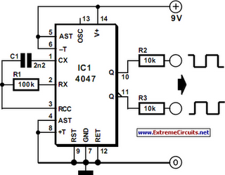
Circuit diagram:

The tester described here consists of a square-wave generator that produces an absolutely symmetrical alternating voltage without any d.c. component. Most logic oscillators are incapable of producing a squarewave signal: they generate rectangular waveforms whose duty cycle hovers around the 50%. The 4047 used in the tester has a binary scaler at its output that guarantees symmetry. The oscillator frequency is about 1 kHz. It may be powered from a 3–9 V source. Normally, this will be a battery, but a variable power supply has advantages. It shows at which voltage the display works satisfactorily and also that there is a clear relationship between the level of the voltage and the angle at which the display is clearly legible.
The tester draws a current not exceeding 1 mA. The test voltage must at all times be connected between the common terminal, that is, the back plane, and one of the segments. If it is not known which of the terminals is the back plane, connect one probe of the tester to a segment and the other successively to all the other terminals until the segment becomes visible. Note, however, that there are LCDs with more than one back plane. Therefore, if a segment does not become visible, investigate whether the display has a second back plane terminal.
