Home » Circuits
Neon Flasher Runs From 3V Supply
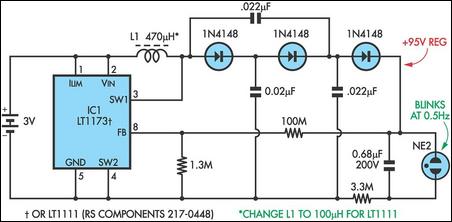
A neon indicator typically requires at least 70V to fire it and normally would not be contemplated in a battery circuit. However, this little switchmode circuit from the Linear Technology website (www.linear-tech.com) steps up the 3V battery supply to around 95V or so, to drive a neon with ease. The circuit has two parts: IC1 operating as step-up converter at around 75kHz and a diode pump, consisting of three 1N4148 diodes and associated .022µF capacitors. The 3.3MO resistor and the 0.68µF capacitor set the flashing rate to about once every two seconds. The average DC level from the diode pump is set to about 95V by the 100MO feedback resistor to pin 8. The circuit could also use an LT1111 (RS Components Cat 217-0448) which would run at about 20kHz so L1 could be reduced to 100mH and use a powdered iron toroid core from Neosid or Jaycar.Circuit diagram:

