Home » Circuits
Portable 9v Headphone Amplifier
High Quality One-IC unit, Low current consumptionAfter several requests by correspondents, the decision of designing a 9V powered Headphone Amplifier was finally taken. The main requirement was to power the circuit by means of a common, PP3 (transistor radio) alkaline battery. So, implementing a low current drawing circuit was absolutely necessary, though preserving a High Quality performance.
Circuit Diagram:
 Large View
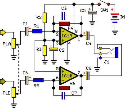
Parts:
P1 = 22K
R1 = 18K
R2 = 68K
R3 = 68K
R4 = 68K
R5 = 18K
R6 = 68K
C1 = 4.7uF-25v
C2 = 4.7uF-25v
C3 = 22pF
C4 = 220uF-25v
C5 = 220uF-25v
C6 = 4.7uF-25v
C7 = 22pF
C8 = 220uF-25v
J1 = 3.5mm Stereo Jack
B1 = 9V Alkaline Battery
IC1 = NE5532-34
SW1 = SPST Toggle Switch
More:
P1 = 22K
R1 = 18K
R2 = 68K
R3 = 68K
R4 = 68K
R5 = 18K
R6 = 68K
C1 = 4.7uF-25v
C2 = 4.7uF-25v
C3 = 22pF
C4 = 220uF-25v
C5 = 220uF-25v
C6 = 4.7uF-25v
C7 = 22pF
C8 = 220uF-25v
J1 = 3.5mm Stereo Jack
B1 = 9V Alkaline Battery
IC1 = NE5532-34
SW1 = SPST Toggle Switch
More:
- The appearance of the 5534 low-noise op-amp at a reasonable price was much appreciated by audio designers. It is now difficult or impossible to design a discrete stage that has the performance of the 5534 without quite unacceptable complexity.
- 5534 op-amps are now available from several sources, in a conventional 8-pin d.i.l. format. This version is internally compensated for gains of three or more, but requires a small external capacitor (5-15pF) for unity-gain stability. The 5532 is a very convenient package of two 5534s in one 8-pin devices with internal unity-gain compensation, as there are no spare pins.
- The 5534/2 is a low-distortion, low-noise device, having also the ability to drive low-impedance loads to a full voltage swing while maintaining low distortion. Furthermore, it is fully output short-circuit proof. Therefore, this circuit was implemented with a single 5532 chip forming a pair of stereo, inverting amplifiers, having an ac gain of about 3.5 and capable of delivering up to 3.6V peak-to-peak into a 32 Ohm load (corresponding to 50mW RMS) at less than 0.025% total harmonic distortion (1kHz & 10kHz).
Source : www.redcircuits.com