Home » Circuits
PWM Dimmer/Motor Speed Controller
This is yet another project born of necessity. It's a simple circuit, but does exactly what it's designed to do - dim LED lights or control the speed of 12V DC motors. The circuit uses PWM to regulate the effective or average current through the LED array, 12V incandescent lamp (such as a car headlight bulb) or DC motor. The only difference between the two modes of operation is the addition of a power diode for motor speed control, although a small diode should be used for dimmers too, in case long leads are used which will create an inductive back EMF when the MOSFET switches off.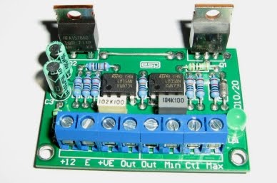 Photo of Completed PWM Dimmer/Speed Control
The photo shows what a completed board looks like. Dimensions are 53 x 37mm, so it's possible to install it into quite small spaces. The parts used are readily available, and many subsitiutions are available for both the MOSFET and power diode (the latter is only needed for motor speed control). The opamps should not be substituted, because the ones used were chosen for low power and their ability to swing the output to the negative supply rail.
Note that if used as a motor speed controller, there is no feedback, so motor speed will change with load. For many applications where DC motors are used, constant speed regardless of load is not needed or desirable, but it is up to you to decide if this will suit your needs.
Description
First, a description of PWM is warranted. As the pot is rotated clockwise, the input voltage changes linearly with rotation. At first, the voltage is such that the comparator output is just narrow spikes, which turn the MOSFET on for a very short period. Average current is low, so connected LEDs will be quite dim, or a motor will run (relatively) slowly. As the input voltage coming from the pot increases, the MOSFET is on for longer and longer, so increasing power to the load.
 Figure 1 - PWM Waveform Generation
Figure 1 shows how the PWM principle works. The red trace is the triangle wave reference voltage, and the green trace is the voltage from the pot. When the input voltage is greater than the reference voltage, the MOSFET turns on, and current flows in the load. Because the frequency is relatively high (about 600Hz), we don't see any flicker from the LEDs, but the tone is audible from a motor that's PWM controlled. The PWM signal is shown in blue. The average current through the load is determined by the ratio of on-time to off-time, and when both are equal, the average current is exactly half of that which would be drawn with DC.
 Figure 2 - Dimmer/Speed Controller Schematic
The circuit is shown in Figure 2. U1 is the oscillator, and generates a triangular waveform. R4 and R5 simply set a half voltage reference, so the opamps can function around a 6V centre voltage. U2A is an amplifier, and its output is a 10V peak to peak triangle wave that is used by the comparator based on U2B. This circuit compares the voltage from the pot with the triangle wave. If the input voltage is at zero, the comparator's output remains low, and the MOSFET is off. This is the zero setting.
In reality, the reference triangle waveform is from a minimum of about 1.5V to a maximum of 9.5V, so there is a small section at each end of the pot's rotation where nothing happens. This is normal and practical, since we want a well defined off and maximum setting. Because of this range, for lighting applications, an industry standard 0-10V DC control signal can be used to set the light level. C-BUS (as well as many other home automation systems) can provide 0-10V modules that can control the dimmer.
While a 1N4004 diode is shown for D2, this is only suitable if the unit is used as a dimmer. For motor speed control, a high-current fast recovery diode is needed, such as a HFA15TB60PBF ultra-fast HEXFRED diode. There are many possibilities for the diode, so you can use whatever is readily available that has suitable ratings. The diode should be rated for at least half the full load current of the motor, and the HFA15TB60PBF suggested is good for 15A continuous, so is fine with motors drawing up to 30A.
Construction
While it's certainly possible to build the dimmer on veroboard or similar, it's rather fiddly to make and mistakes are easily made. Also, be aware that because of the current the circuit can handle, you will need to use thick wires to reinforce some of the thin tracks. This is even necessary for the PCB version. Naturally, I recommend the PCB, and this is available from ESP. The board is small - 53 x 37mm, and it carries everything, including the screw terminals. The PCB is double-sided with plated-through holes, and has solder masks on both sides.
The MOSFET will need a heatsink unless you are using the dimmer for light loads only. It is necessary to insulate the MOSFET from the heatsink in most cases, since the case of the transistor is the drain (PWM output). For use at high current and possible high temperatures, the heatsink may need to be larger than expected. Although the MOSFET should normally only dissipate about 2W or so at 10A, it will dissipate a lot more if it's allowed to get hot. Switching MOSFETs will cheerfully go into thermal runaway and self destruct if they have inadequate heatsinking. You may also use an IGBT (insulated gate bipolar transistor) - most should have the same pinouts, and they do not suffer from the same thermal runaway problem as MOSFETs.
As noted above, there are many different MOSFETs (or IGBTs) and fast diodes that are usable. The IRF540 MOSFET is a good choice, and being rated 27A it has a generous safety margin. There are many others that are equally suitable - in fact any switching MOSFET rated at 10A or more, and with a maximum voltage of more than 20V is quite ok.
Testing
Connect to a suitable 12V power supply. When powering up for the first time, use a 100 ohm "safety" resisor in series with the positive supply to limit the current if you have made a mistake in the wiring. The total current drain is about 2.5mA with the pot fully off, rising to 12.5mA when fully on. Most of this current is in the LED, which is also fed from the PWM supply so you can see that everything is working without having to connect a load.
Make sure that the pot is fully anti-clockwise (minimum), and apply power. You should measure no more than 0.25V across the safety resistor, rising to 1.25V with the pot at maximum. If satisfactory, remove the safety resistor and install a load. High intensity LED strip lights can draw up to ~1.5A each, and this dimmer should be able to drive up to 10 of them, depending on the capabilities of the power supply and the size of the heatsink for the MOSFET.
source: http://sound.westhost.com/project126.htm