Home » Circuits
Reservoir Pump Controller
This circuit operates an automotive windscreen washer pump to fill a 20-litre drum from a 205-litre water reservoir. The drum is suspended above a drip line, which irrigates a vegetable garden. Two stainless steel probes mounted in the drum act as sensors for the system. One probe is positioned at the high water mark, the other at about half-full. The pump power is switched by a 12V automotive relay (RLY1). Two op amps (IC1a & IC1b) connected as voltage comparators form the basis of the circuit. Initially, assume a falling water level with the pump switched off. When the water level exposes the lower probe, the non-inverting input (pin 5) of IC1b rises to about 7.4V. With trimpot VR2 correctly adjusted, this will be higher than the voltage on pin 6.The output (pin 7) therefore swings high, biasing Q1 into conduction. This in turn causes Q4 to conduct, switching on the relay and starting the pump. In addition, when Q4 switches on it supplies base current to Q3 via a 6.8kO resistor. Initially, this current flows through the 47µF capacitor, but once its base-emitter voltage reaches about 0.6V, Q3 conducts. This action latches Q4 in the "on" state, as its base current can flow to ground via Q3 when Q1 stops conducting – which will occur when the rising water level reaches the low probe. When the water level reaches the high probe, the voltage on the non-inverting input (pin 2) of IC1a decreases markedly due to the conductivity of the water.
Circuit diagram:
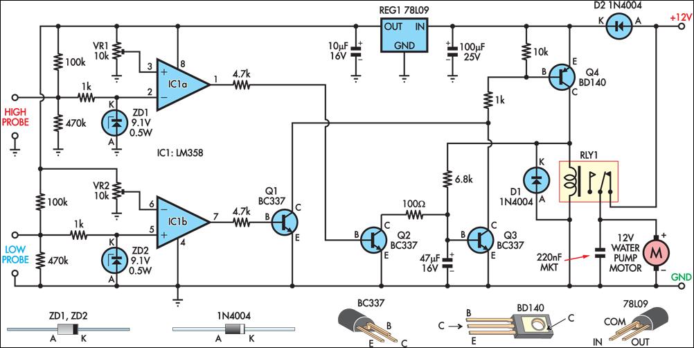
If trimpot VR1 is correctly adjusted, the output (pin 1) swings high, switching on Q2. This discharges the 47µF capacitor and robs Q3 of its base current, switching this transistor off. This in turn switches off Q4 and the relay. The zener diodes and 1kO series resistors at the probe inputs protect the op amp’s high impedance inputs from the effects of static discharge. The 47µF capacitor in parallel with the base-emitter junction of Q1 prevents the latching function from being activated when power is applied to the circuit. The author’s setup is powered from an old car battery charged from a 12V solar panel.
Author: Peter Howarth
Copyright: Silicon Chip Electronics
Copyright: Silicon Chip Electronics