Home » Circuits
Sensitive Overload Sensor
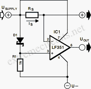
The best way to measure the current in a circuit is to place a sense resistor in the current path. The higher the resistance, the more exact the measurement will be. However, the drawback of a high resistance is that it affects the operation of the circuit in which the measurement is being made. If an active sort of sensor is used, the sense resistance can be kept small. The circuit diagram shows how a sensitive overload indicator can be built using a simple opamp (such as an LF351) and a sense resistor in the current path. A voltage difference is generated between the plus and minus inputs of the opamp with the help of a diode. Usually, the voltage drop across D1 (a Schottky diode) will be 0.2 to 0.3 V. This value can be influenced somewhat by R1, which affects the amount of current that flows through the diode. The larger the value of R1, the smaller the voltage drop across the diode. The inverting input of the opamp is connected to the positive supply voltage following the sense resistor Rs. Consequently, the voltage level at the output of the opamp will be equal to the negative supply voltage, for example –5 V.
 As the current that flows through the sense resistor Rs increases, the voltage on the inverting input of the opamp decreases. As soon as the voltage drop across Rs (= Is × Rs) becomes slightly greater than the voltage drop across D1, the output of the opamp will switch to the positive supply voltage level. An indicator lamp or relay can be connected to the opamp output. The maximum supply voltage for the opamp is ±15 V, so the circuit can readily be used to monitor symmetric power supplies with voltages between 5 and 15V.
