Home » Circuits
Speed Alarm For Cars
In normal suburban driving you pass through so many different speed zones that it can be a nuisance having to switch speed settings. The speed display can also be a distraction. This circuit eliminates the display and the need for speed selection. Each time you exceed a particular speed setting (eg, 40km/h, 50km/h, etc), a piezo buzzer will beep. Speed pulses are fed to the base of Q1 and the resulting waveform at its collector is fed via an RC network to the input of an LM2917 frequency-to-voltage converter, IC1. The resulting voltage is fed to three comparators (IC2d-IC2b) which have the reference voltages at their inverting inputs set by 10-turn trimpots VR1, VR2 & VR3. The output of each comparator is applied via another RC network to the gate of an SCR. The anodes of the three SCRs are commoned connected to the inverting input of the remaining comparator, IC2a.Circuit diagram:
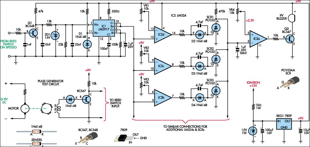
Its non-inverting input is set to +2.3V by trimpot VR4. In use, once you exceed the speed setting for a particular comparator, its associated SCR briefly conducts to pull pin 2 of IC2a low and a short beep is emitted by the piezo buzzer. Then, as you exceed the next speed setting, another beep will be heard. The idea is make each speed setting a few km/h higher than actual so that if you are driving at the correct speed in a given zone, the buzzer will not sound. But as you increase speed, the buzzer will beep once as you exceed the speed setting for each zone. In this way, there is no need to continually switch speed settings as you drive through different zones and you can choose to ignore beeps that are not "illegal".
Author: Col Edwards - Copyright: Silicon Chip Electronics Magazine