Home » Circuits
Telephone Free Indicator
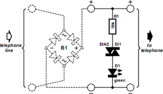
Depending on local regulations and the telephone company you happen to be connected to, the voltage on a free telephone line can be anything between 42 and 60 volts. As it happens, that’s sufficient to make a diac conduct and act like a kind of zener diode maintaining a voltage of 38 V or so. The current required for this action causes the green high-efficiency LED in the circuit to light. Line voltages higher than about 50 V may require R1 to be changed from 10 kΩ to a slightly higher value. When the receiver is lifted, the line voltage drops to less than 15 V (typically 12 V) causing the diac to block and the LED to go out.
The circuit diagram indicates + and – with the phone lines. However, in a number of countries the line polarity is reversed when a call is established. To make sure the circuit can still function under these circumstances, a bridge rectifier may be added as indicated by the dashed outlines. The bridge will make the circuit independent of any polarity changes on the phone line and may consist of four discrete diodes, say, 1N4002’s or similar. Finally, note that this circuit is not BABT approved for connection to the public switched telephone network (PSTN) in the UK.
