Home » Circuits
Two-Wire Temperature Sensor
Remote temperature measurements have to be linked by some sort of cable to the relevant test instrument. Normally, this is a three-core cable: one core for the signal and the other two for the supply lines. If the link is required to be a two-core cable, one of the supply lines and the signal line have to be combined. This is possible with, for instance, temperature sensors LM334 and LM335. However, these devices provide an output that is directly proportional to absolute temperature and this is not always a practical proposition. If an output signal that is directly proportional to the Celsius temperature scale is desired, the present circuit, which uses a Type LM45 sensor, offers a good solution.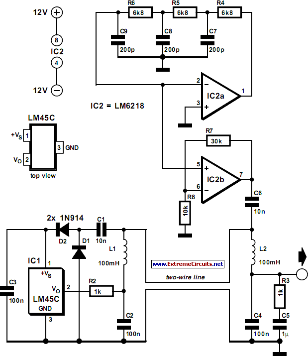
The LM45 sensor is powered by an alternating voltage, while its output is a direct voltage. The supply to the sensor is provided by a sine-wave generator, based on A1 and A2 (see diagram). The alternating voltage is applied to the signal line in the two-core cable via coupling capacitor C6. The sensor contains a voltage-doubling rectifier formed by D1-D2-C1-C2. This network converts the applied alternating voltage into a direct voltage. Resistor R2 isolates the output from the load capacitance, while choke L1 couples the output signal of the sensor to the signal line in the cable.
Choke L1 and capacitor C2 protect the output against the alternating voltage present on the line. At the other end of the link, network R3-L2-C4 forms a low-pass section that prevents the alternating supply voltage from combining with the sensor output. Capacitor C5 prevents a direct current through R3, since this would attenuate the temperature-dependent voltage. The output load should have a high resistance, some 100 kΩ or even higher. The circuit draws a current of a few mA.