Home » Circuits
Voltage Regulator Calculation
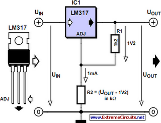
Before you can design an adjustable voltage regulator into your circuit, or do a redesign, you need to calculate the values for two resistors. This is not difficult in itself, but actually finding the right resistors may pose problems. Fortunately a trick is available to make it all much easier. With most adjustable voltage regulators like the LM317 and LM337, the input voltage has to be 1.2 to 1.25 volts above the desired output voltage. This is because the voltage at the ADJ (adjust) input is internally compared to a reference voltage with that value. The reference voltage always exists across R1.Circuit diagram:

Together with preset R2 it determines the current flowing through the ADJ pin, as follows: Vout = VREF [1+(R2/R1)]+I ADJ R2 If for the sake of convenience we ignore I ADJ, enter the reference voltage (1.2 V) and for R1 select a value of one thousand times that voltage (i.e., 1.2 k?) then the equation is simplified to: R2 = 1000 (Vout – 1.2) In practice, simply determine the voltage drop across R2 (output voltage minus reference voltage) and you get your resistance value directly in kilo-ohms. For example, for 5 V R2 becomes 5–1.2 = 3.8 k? which is easiest made by connecting 3.3k and 470R resistors in series. In the case of relatively low voltages, smaller resistor values are recommended. This is because sufficient current needs to flow to enable the voltage regulator to do its job. A simple solution is to choose, say, 120 ? for R1. R2 then becomes: R2 = 100 (Vout – 1.2)
Author: Victor Himpe
Copyright: Elektor Electronics
Copyright: Elektor Electronics
